Do you have a question about the Bugera 1990 and is the answer not in the manual?
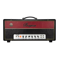
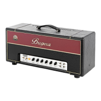
Expresses gratitude and congratulations to the user for purchasing the BUGERA 1990 amplifier.
Alerts to high voltage, risk of electric shock from terminals, and the danger of opening the unit.
Covers safe operation, avoiding liquids, proper cleaning, ventilation, and grounding.
Provides legal disclaimers and directs to warranty information online.
Stresses correct impedance matching and using approved loudspeaker cables to prevent damage.
Guides on inspecting for damage, proper storage, and keeping the unit away from children.
Advises on proper installation placement to avoid interference and ensure optimal sound quality.
Highlights the importance of adequate air supply and proper grounding for safety and performance.
Explains the POWER, STANDBY switches for operation and the CHANNEL button for switching between Clean/Lead.
Details the VOLUME and REVERB rotary knobs for adjusting sound levels and reverb effects for each channel.
Describes the GAIN, PRESENCE, TREBLE, MID, and BASS controls for tone adjustment and distortion.
Identifies the 1/4" INPUT jack for connecting your electric guitar.
Emphasizes the absolute necessity of connecting a loudspeaker before powering on the amplifier.
Details the FOOTSW, SEND/RETURN jacks for effects, and RECORDING/DIRECT outputs.
Covers the paralleled LOUDSPEAKER outputs and the IMPEDANCE switch for speaker cabinet matching.
Explains the POWER MODE switch, fuse replacement, and the IEC MAINS connector for power.
Warns about hot rear panel components and the critical requirement to always use a connected loudspeaker.
Describes the CLEAN and LEAD switches on the footswitch for channel selection.
Identifies the locations of preamp valves (ECC83/ECC83A) and power amp valves (5881).
Explains the use of the BIAS TEST connector and BIAS ADJUST control for power valve biasing.
Warns of lethal high voltages inside and advises that all maintenance be done by qualified personnel.
Provides instructions for connecting one or two speaker cabinets, focusing on impedance matching.
Details how to set the IMPEDANCE switch based on speaker cabinet configurations using a table.
Repeats warnings about hot valves and the essential need for a connected loudspeaker.
Illustrates a setup using an external effects unit connected via the FX LOOP.
Shows signal routing for recording via a mixer and amplifying sound through a PA system.
Explains the structure and function of the unbalanced 1/4" TS mono jack connectors.
Details valve types, impedance, and input/output levels for the preamp and effects sections.
Lists power amp valve types, output power, and loudspeaker connector specifications.
Provides information on power consumption, mains voltage, fuse ratings, physical dimensions, and weight.
Confirms compliance with FCC rules for Class B digital devices and potential radio frequency energy.
Outlines measures for users to correct radio or television interference if it occurs.
Warns that unauthorized modifications to the equipment can void the user's operating authority.