Page 15
SERVICE
This section provides procedures for testing and
replacing various major components used in this
brewer should service become necessary. Refer to
Troubleshooting
for assistance in determining the
cause of any problem.
WARNING - Inspection, testing, and repair of electri-
cal equipment should be performed only by qualified
service personnel. The brewer should be unplugged
when servicing, except when electrical tests are re-
quired and the test procedure specifically states to
plug in the brewer.
NOTE: All illustrations in the service section of this
manual are of a CWTF Model except where specified.
COMPONENT ACCESS
WARNING - Disconnect the brewer from the power
source before the removal of any panel or the replace-
ment of any component.
All components are accessible by the removal of
the top cover, front inspection panel and warmer
plate(s).
The top cover is attached with one #4-40 screw.
The front inspection panel is attached with four #6-
32 screws on CWTF Models, and six #6-32 screws on
CWTF-APS, TS & TC Models.
The warmer assembly (CWTF Models) is attached with
three #4-40 screws.
Contents
Control Thermostat............................................. 16
Limit Thermostat ................................................ 17
ON/OFF Switch.................................................... 18
Solenoid Valve (Inlet) ......................................... 19
Start Switch (Brew) ............................................ 20
Tank Heater(s) .................................................... 21
Tank Heater Switch ............................................. 23
Voltage Selector Switch ...................................... 25
Thermal Fuse ...................................................... 26
Digital Timer ....................................................... 27
Warmer Element ................................................. 29
Wiring Diagrams................................................ 30
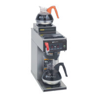
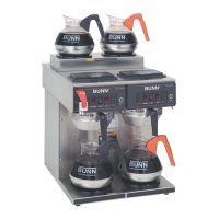
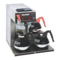
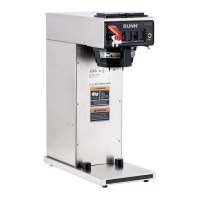
FIG. 1 COMPONENT ACCESS
P1417
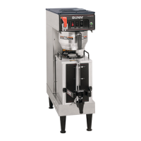
CWTF MODELS
CWTF MODELS
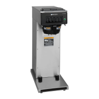
CWTF-APS
36102 090203