15. Move the probe’s flat end to the dispenser housing.
The indication must be 0.
16. Move the probe’s flat end away from the dispenser
housing. The indication should again be:
a.) 100 to 120 volts ac for 100 to 120 volt models,
b.) 200 to 240 volts ac for 200 to 240 volt models,
c.) 230 volts ac for 230 volt models.
17. Disconnect the dispenser from the power source.
If voltage is present as described, reinstall the probe,
the level control board and level probe are operating
properly.
If voltage is not present as described, check the pink
probe wire.
Removal and Replacement:
1. Remove all wires from the level control board.
SERVICE (cont.)
Liquid Level Board (cont.) (H5M & HW2 Only)
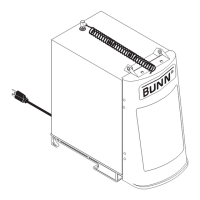
FIG. 12 LIQUID LEVEL BOARD WIRING
BLU to Solenoid (T-1)
BLK to Overflow Safety Switch (T-2)
WHI to Terminal Block (T-3)
PNK to Level Probe (T-4)
P1784
2. Remove two #8-32 screws holding level control
board and mounting bracket to the component
bracket.
3. Install the new level control board and mounting
bracket to the component bracket.
4. Refer to FIG. 12 when reconnecting the wires.
24
 Loading...