Page 19
SERVICE (cont.)
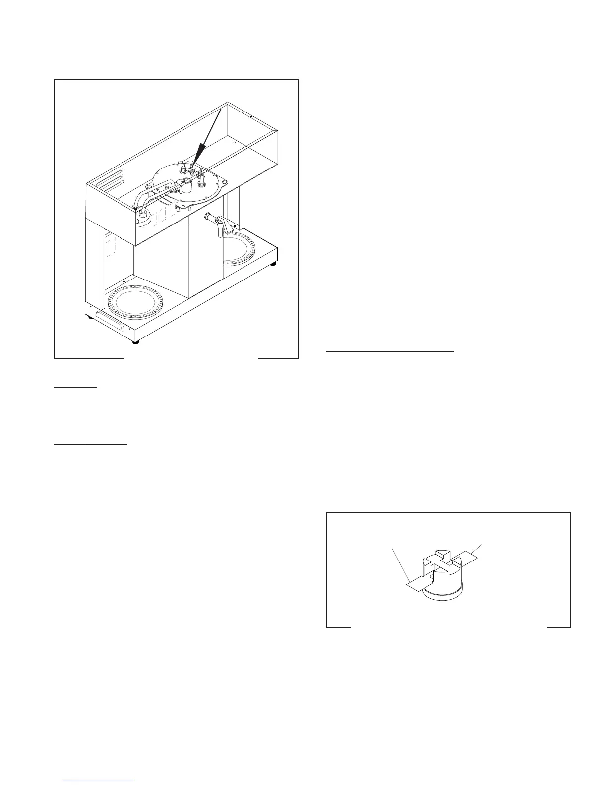
LIMIT THERMOSTAT
Location:
The limit thermostat is located on the tank lid be-
tween the tank heater terminals.
Test Procedure:
1. Disconnect the brewer from the power source and
remove the blue wire from the limit thermostat.
2. With a voltmeter, check the voltage across the blue
wire removed from the limit thermostat and the
white wire on the tank heater terminal when the
control thermostat is turned “ON” (fully clock-
wise). Connect the brewer to the power source.
The indication must be 120 volts ac.
3. Disconnect the brewer from the power source.
P
N
:
6
5
8
FIG. 10 LIMIT THERMOSTAT
P1983.40
If voltage is present as described, reconnect the blue
wire and proceed to #4.
If voltage is not present as described, refer to the
Wiring Diagram
and check the brewer wiring harness.
4. Remove the black wire from the limit thermostat.
5. With a voltmeter, check for voltage across the ex-
posed terminal of the limit thermostat and the
white wire on the tank heater terminal when the
control thermostat is turned “ON” (full clockwise).
Connect the brewer to the power source. The in-
dication must be 120 volts ac.
6. Disconnect the brewer from the power source.
If voltage is present as described, reconnect the black
wire, the limit thermostat is operating properly.
If voltage is not present as described, replace the limit
thermostat.
Removal and Replacement:
1. Remove both wires from the limit thermostat ter-
minals.
2. Carefully slide the limit thermostat out from un-
der the retaining clip.
3. Carefully slide the new limit thermostat into the
retaining clip.
4. Refer to FIG. 11 when reconnecting the wires.
FIG. 11 LIMIT THERMOSTAT TERMINALS
P1984.60
BLU to Control
Thermostat
BLK to Tank
Heater
10179 060100