
L
Lori MillerAug 18, 2025
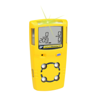
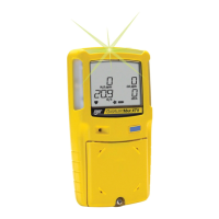
Why does my BW Technologies GasAlertMax XT II detector not accurately measure gas?
- EEric SaundersAug 19, 2025
If your detector isn't accurately measuring gas, it could be because the sensor requires calibration (calibrate the sensor), the detector's temperature differs from the gas temperature (allow the detector to reach ambient temperature before use), or the sensor filter is blocked (replace the sensor filter).