OPERATION
6
Press the test button of the transmitter. Both LED lights of the
transmitter and receiver should blink simultaneously when the test
button is pressed. It indicates that both the transmitter and the receiver
are working in good condition.
Attach the hot shoe of the transmitter to the hot shoe of the camera.
If your camera does not have a hot shoe, connect the transmitter to the
camera via PC sync cable (CA-100).
More than one receiver can be used to work with a transmitter. Extra V4
receivers and connection cables can be purchased separately for your
set up.
4.
5.
6.
7.
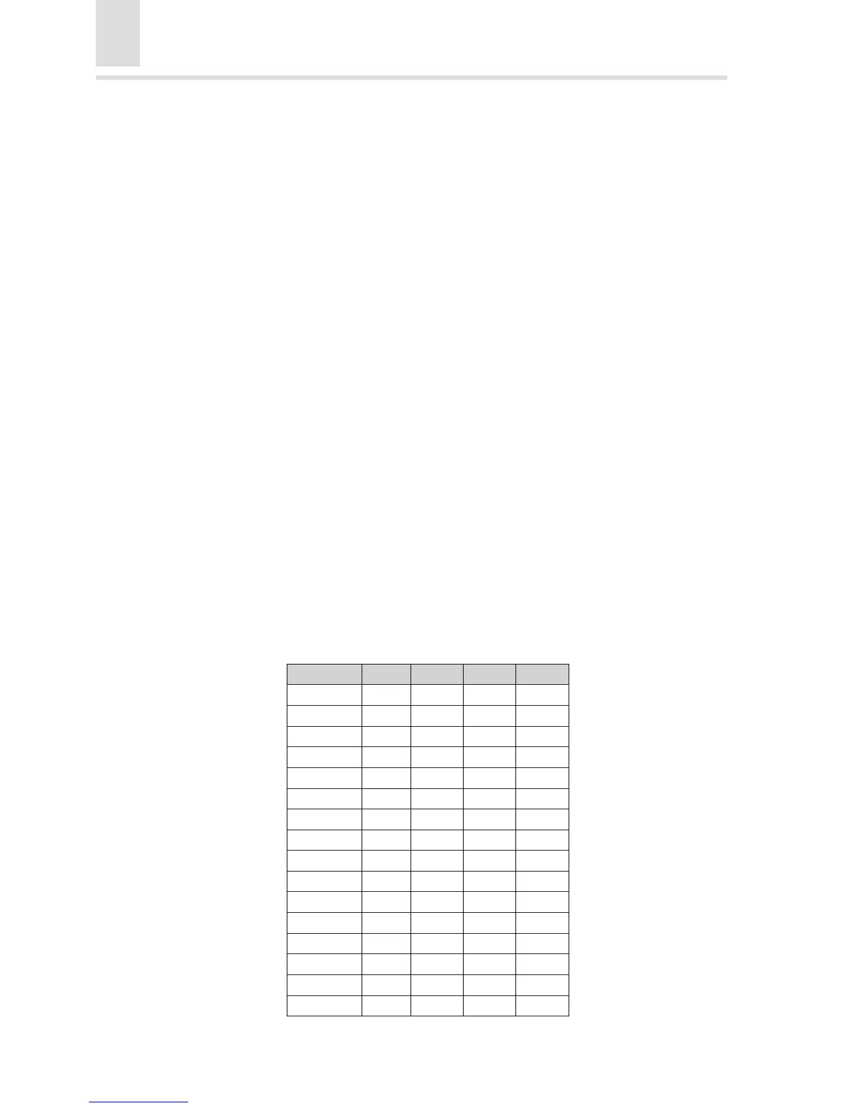
Channel Setup
There are four small switches located at the bottom of the transmitter and
the top of the receiver. Sixteen channels can be tuned according to
dierent combinations of the switches. Only when the channel of the
transmitter matches that of the receiver will the external ash be triggered
o.
The combinations are as follows (“0” stands for UP while “1” stands for
DOWN):