2
Installation Guidelines
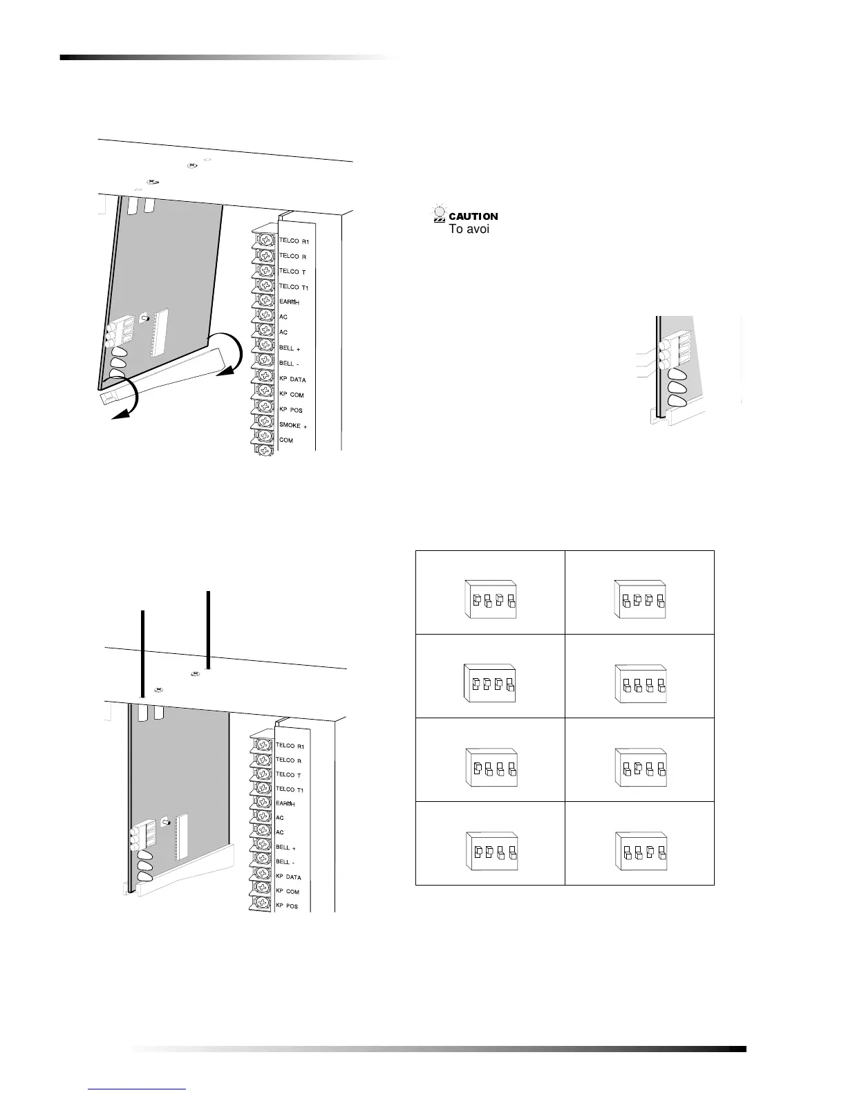
3. Install the module into the cabinet by turning the stand-
off sideways, then slide the module up onto the ground
plane screw posts (see Figure 3).
Figure 3. Installing the Module into the Cabinet
4. Turn the standoff so the slot is facing up, insert the
back corner of the module into the standoff slot, then
press up at the front of the standoff and tighten the
standoff screw.
5. Insert the antennas through the holes on top of the cabi-
net and into the module antenna sockets (see Figure 4).
Figure 4. Inserting the Antennas
Wiring, Module Number DIP Switch
Settings, and Power Up
The following steps describe wiring the module to the con-
trol panel, setting the module number DIP switches, and
powering up the control panel.
1. Remove power (if applied) from the control panel.
&$87,21
To avoid possible equipment damage or personal
injury, remove power from the control panel before
making any wiring connections to the module.
2. Connect the module power, ground, and data terminals
to the control panel power, common, and data terminals
using 22-gauge or larger, stranded wire (see Figure 5).
Figure 5. Wiring the Module Power and Data Terminals
to the Panel Power and Data Terminals
3. Set the module DIP switches to the desired module
number (see Table 1).
9740G04A.DS4
9740G10A.DS4
Table 1. Receiver Module Number Settings
Module Number 32 Module Number 33
Module Number 34 Module Number 35
Module Number 36 Module Number 37
Module Number 38 Module Number 39
9 7 4 0 G 1 4 B . D S 4
P O W E R + ( T O P A N E L A U X P W R + )
G N D ( T O P A N E L C O M )
D A T A ( T O P A N E L K P D A T A )
O N
1 2
43
E D G O N
1 2
43
E D G
O N
1 2
43
E D G
ON
1 2
43
EDG
O N
1 2
43
E D G O N
1 2
43
E D G
O N
1 2
43
E D G O N
1 2
43
E D G