Capital Automotive Equipment
Model:4PG8000
and the power unit mounting plate on the Power Side post, using four M8 hex head bolts and nuts
supplied.
11. According to the hydraulic layout diagram, connect the oil pipes.
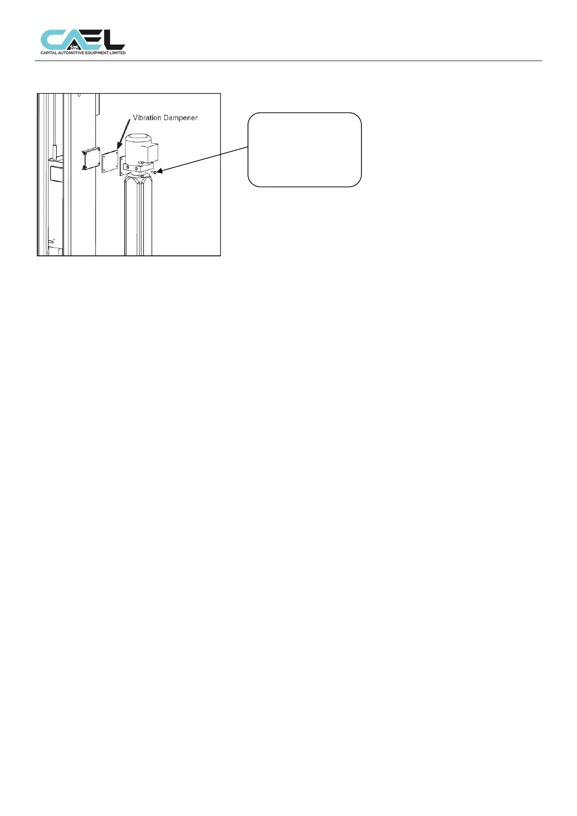
• Attach the power unit onto the support mounted on the power side column and secured with included
screws and washers.
• Route the hydraulic hoses referring the below photo.
• Tighten the fittings thoroughly.
Warning: When routing the hose, make sure to fit clips in the central position to keep the hose off the
moving steel cables under the base plate. Make sure to keep the hoses clean from dust.
12. Installation of limit switch
Fix the limit switch onto the power-side column in the position as shown in the figure 14 by using the
supplied screws.
And limit switch cable and motor cable are in parallel connection.
Raise the lift at a height of 70.8” (1800mm) to check for the proper function;
If the switch is not functioned properly, adjust the position of the switch lever
Chapter 5 Adjustment
5.1 Preparation before adjustment
Upright adjustment:
Use plumb to fix the top of post and check whether its install position is upright.
Then hammer the expanded bolt and tighten the ground bolt cap.
Only can hammer the expanded bolt after the expired period of the concrete and the gap between base
plate and ground surface must be filled with iron plate or concrete and then tighten the anchor bolts!
5.2 Process of adjustment
• Check whether the connection of power is correct, pay attention to the turning of 1 phase motor.
• Ensure all bolts are tightened enough.
• Press and HOLD “UP” button on motor, it will go up.
Press UP button on motor, the platform will go up 1 or 2 inch and lock latches leave the lock block, and
press and hold LOCK RELEAE HANDLE, then
Pull the LOWERING HANDLE on the power unit until the lift
has descended completely.
•
M8 x1.25 x 35mm
hex head bolts, M8
flat washers and
M8 Nylock nuts