INSTALLATION
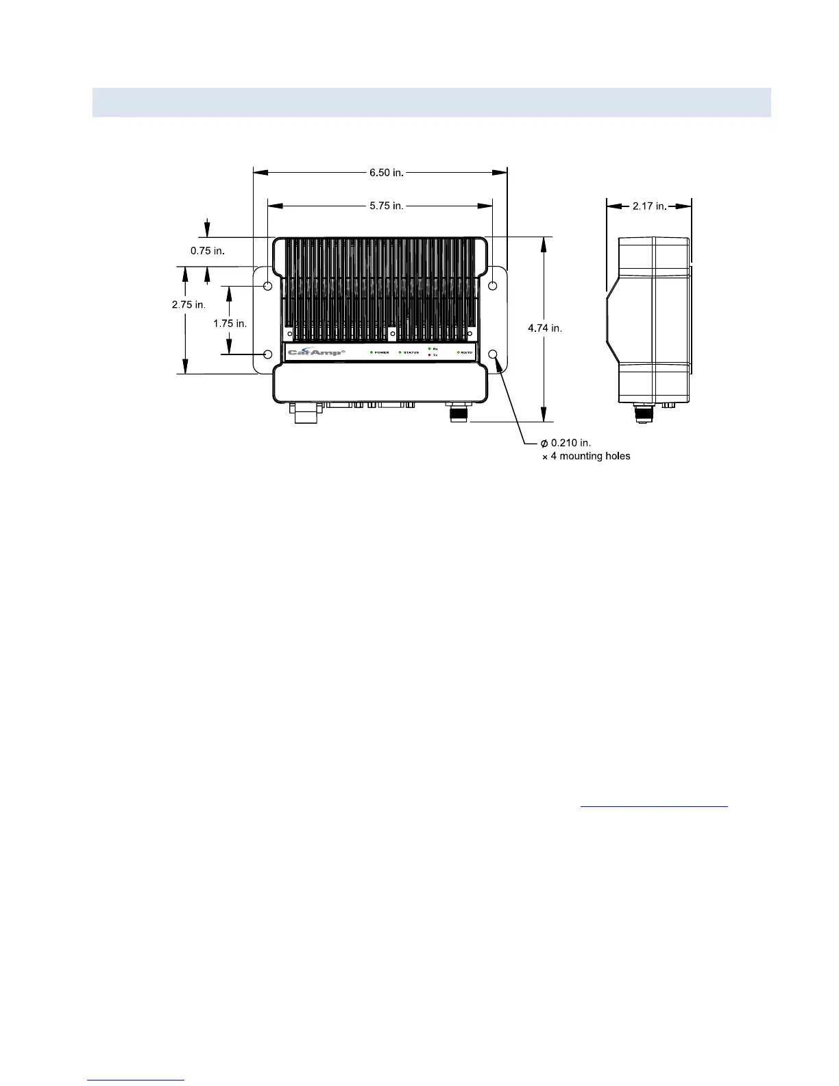
As noted earlier, the Guardian footprint is different than the DL-3400.
Figure 5 shows the mechanical dimensions for the Guardian. When mounting the Guardian, orientation should allow
unrestricted airflow from the heat sink fins. If location, heat dissipation, or duty cycle are a concern, the addition of the
Guardian Fan Kit may be considered. See Table 9 for a list of fan kits that are available for use with the Guardian.
Contact your sales representative for further information.
Antenna connection is a TNC Female 50 ohm connector. See Table 10 for available Coaxial Adapter Cables from
CalAmp.
Analog connection is an 8-pin plug-in connector with tension clamp contacts. Radio control and signal connections are
made by inserting either insertion tool PN 250-5006-001 or a small screwdriver into the connector.
- Strip wire to a maximum of 5/16 in. or 7 mm for insertion into the connector.
- Wire size is from 28 AWG to 18 AWG and can be either stranded or solid.
- Insert insertion tool or screwdriver into the socket corresponding to the appropriate pin and insert wire.
- Remove insertion tool or screwdriver and wire should be locked in place.
- Follow the same procedure for removal of wires if necessary.
For technical assistance, contact CalAmp Wireless Network Group Technical Service at
wngsupport@calamp.com.
Guardian™ Serial Modem or Analog Radio for Licensed Spectrum PN 001-5006-000 Rev. 3 | Page 70