Temperature probes
Flow probe length
Return probe length
Probe type
Working temperature range limits
Temperature difference limits
Measurement sensitivity
Flow meter
Dimensions/Connection
Body
Type of hydraulic connection
Nominal pressure
Max. temperature of the medium
Mounting
Pulse output
Permanent ow rate
Minimum ow rate
Maximum ow rate
Electric supply
Microprocessor calculator unit
Metrological specications
Accuracy class
Centralised transmission
Ambient temperature range limits
Ambient classication
Energy unit of measurement
Electric supply
Protection class
Pulse inputs
Technical specications
in compliance with EN 1434-1 - MID 2014/32/EU
class 2
according to M-Bus/ MODBUS RTU protocol on RS-485
5–45
MID 2014/32/EU E1-M1
8-digit display
24 V (+10 % / -5 %) (ac) - 1 W - 50 Hz
in accordance with DIN 40050: IP 54
class IB in accordance with EN 1434-2
1,9
1,9
NTC
10–90 (HEATING) - 2–25 (COOLING)
3–80 (HEATING) - 3–20 (COOLING)
≤0,05
bar
°C
l/h
l/h
l/h
°C
kWh
PN
Qp
Qi
Qs
m
m
°C
K
°C
90
preferably horizontal
class OA-OC in accordance with EN1434-2
see table 1 and 2
see table 1 and 2
see table 1 and 2
lithium battery, life 12 years
p
Code
The CONTECA
®
heat meter is supplied with accessories for installation, probes positioning and subsequent lead sealing.
Code
DN G
F
E
C
A
B
D
DN A CB D PN
PN
2 x Y-pockets (the flow pocket is fitted with a strainer mesh)
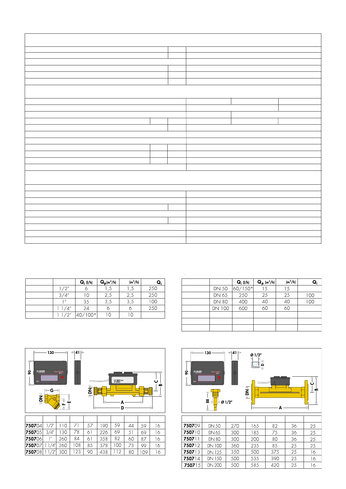
TABLE 1 - Flow rate limit - Connections from 1/2” to 1 1/2”:
Code
Connections
Code
Connections
2 x 1/2” weld sleeves with brass pocket to 1 lead sealing kit
* vertical installation
* vertical installation
TABLE 2 - Flow rate limit - Connections from DN 50 to DN 200:
1000 100
DN 125 100
1500 150DN 150 100
2500 250
100
150
250DN 200 100
100
Q
s
Q
s
750704
750705
750706
750707
750708
750709
750710
750711
750712
750713
750714
750715
Q /
p
100*/250
100*/250
p
Q /
p
Dimensions
2
Flanged EN 1092-1
Male thread ISO 228
Brass
DN 125–DN 200
1/2”–1 1/2”
DN 50–DN 100
Steel P235GH
PN 16
PN 16
PN 25
N.B. The ow meter must be installed between two rectilinear sections, measuring 10 times the pipe diameter upstream and 3 times the pipe diameter downstream.
 Loading...