Guidelines for rst installation
It is good practice to install shut-off valves upstream and downstream from the meter in order to facilitate installation and maintenance, if
required.
A ltering device must be provided upstream of the ow rate meter in order to protect the meter.
With a diameter of 1/2” to 1 1/2”, this strainer is already inside the ow temperature pocket.
Installation procedure
• Install the hydraulic components (probe pocket and ow meter) in accordance with the guidelines provided in paragraph “Hydraulic installation
diagrams” on this page;
• After installation, wash the pipes and carry out a pressurised test;
• Check the saturation level of the strainers and, if necessary, clean them;
• After completing installation of the hydraulic parts, install the CONTECA
®
EASY ULTRA electronic unit: follow the instructions for electrical
connection on pages 5 and 6.
• Insert the temperature probes into the corresponding pockets in line with the ow direction: the ow probe (red label) must be installed on the
ow pipe, while the return probe (blue label) should be on the return pipe.
• At the end of the installation process the main heat meter components (electronics unit, temperature probes and volume meter) should undergo
lead sealing. Lead sealing must be performed by qualied technicians in accordance with the instructions on pages 9 and 10 (“Lead
sealing procedure”).
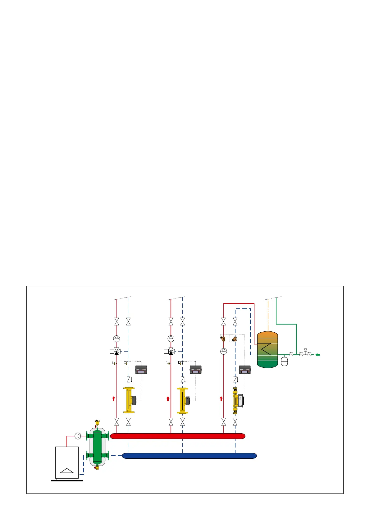
1) Guideline diagram of the system with metering on the multiple circuit manifold.
EASY
CONTECA
EASY EASY
CONTECA
EASY EASY
CONTECA
EASY
M07 1259
07185865
M07 1259
07185865
M07 1259
07185865
Hydraulic installation diagrams
The ow meter must be tted on the return pipe.
The hydraulic diagrams provided below show:
a) Flow meter positioning
The ow meter should preferably be installed in a horizontal position, with the axis of the turbine vertical
, observing
the ow direction as indicated
by the arrow on the body. The position of the ow meter, where possible, should result in a zero ow rate when there is no service.
b) Probe positioning
The temperature probes (by means of the pocket or sleeve according to the DN) must be positioned on the corresponding ow/return pipes. The
corresponding pipes are the pipes carrying the same ow rate when the ow has started.
3
 Loading...