Operating information
Accumulated energy is stored in a non-volatile memory device
(EEPROM) each time the unit of measurement is competed (1 kWh);
at the same time this increase results in updating of the display (see
“User information cycle”).
6
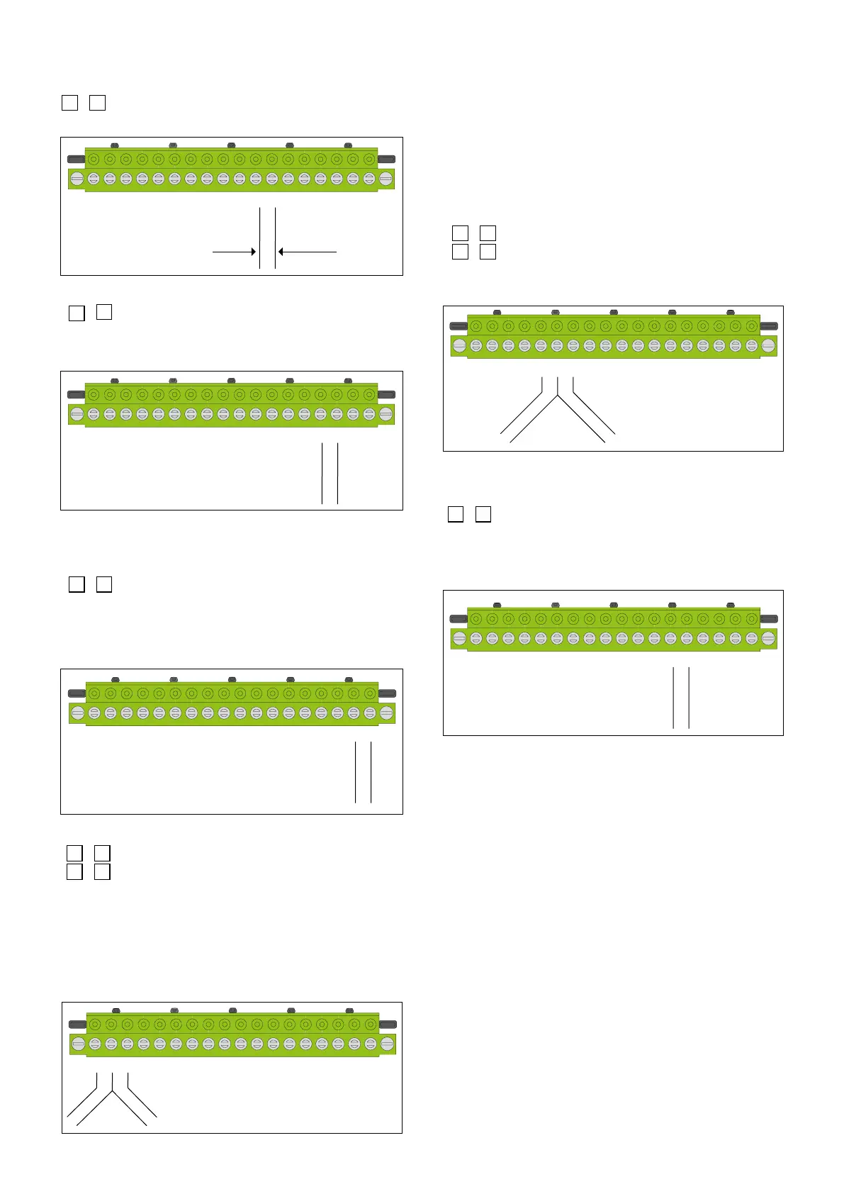
ELECTRONICS BOX REAR PART
CABLE ROUTE
TEAR-PROOF CABLE CLIP
AA
AA
1234 56789101112131415161718
1234 56789101112131415161718
24 V (ac)
1234 56789101112131415161718
1234 5 6 7 8 910 11 12 13 14 15 16 17 18
RS485
1234 56789101112131415161718
Cooling units
1234 56789101112131415161718
1234 56789101112131415161718
digital input
A
B
Heating units
4
th
pulse input
3
rd
pulse input
pulse input
blue wire
white wire
• Heating/cooling ow meter
11
-
12
Flow meter pulse input.
11 (blue wire) 12 (white wire)
• Electric supply
15
-
16
Centralised 24 V (ac) electric supply line
The
24 V (ac) electric supply line must only be used
for heat
meters and must not be under the user’s control.
ELECTRONICS BOX REAR PART
CABLE ROUTE
TEAR-PROOF CABLE CLIP
AA
AA
1234 56789101112131415161718
1234 56789101112131415161718
24 V (ac)
1234 56789101112131415161718
1234 5 6 7 8 910 11 12 13 14 15 16 17 18
RS485
1234 56789101112131415161718
Cooling units
1234 56789101112131415161718
1234 56789101112131415161718
digital input
A
B
Heating units
4
th
pulse input
3
rd
pulse input
pulse input
blue wire
white wire
• Data centralisation
If centralised data transmission via BUS is used, the following
connection plan must be implemented:
17
-
18
RS-485 polarised transmission Bus
17 Tx (RS-485-B) 18 Rx (RS-485-A)
For the transmission bus, use 2 x 1 mm
2
cable, preferably of the
twisted type. Note: Transmission polarisation must be fully
observed
ELECTRONICS BOX REAR PART
CABLE ROUTE
TEAR-PROOF CABLE CLIP
AA
AA
1234 56789101112131415161718
1234 56789101112131415161718
24 V (ac)
1234 56789101112131415161718
1234 5 6 7 8 910 11 12 13 14 15 16 17 18
5
1234 56789101112131415161718
Cooling units
1234 56789101112131415161718
1234 56789101112131415161718
digital input
A
B
Heating units
4
th
pulse input
3
rd
pulse input
pulse input
blue wire
white wire
• Enery pulse outputs - codes 755881/755882
2
-
3
Remote heating units totaliser output (kWh) (OC type)
1
-
2
Remote cooling units totaliser output (kWh) (OC type)
These outputs can be connected to our product code 755890
(remote energy totaliser) or a general supervisor.
Output specications:
1 IMP = 1 kWh - open collector contact
Pulse duration: 120 ms
24 V (dc) - 50 mA
Maximum frequency = 1 Hz
ELECTRONICS BOX REAR PART
CABLE ROUTE
TEAR-PROOF CABLE CLIP
AA
AA
1234 56789101112131415161718
1234 56789101112131415161718
24 V (ac)
1234 56789101112131415161718
1234 5 6 7 8 910 11 12 13 14 15 16 17 18
RS485
1234 56789101112131415161718
s
1234 56789101112131415161718
1234 56789101112131415161718
digital input
A
B
Heating units
4
th
pulse input
3
rd
pulse input
pulse input
blue wire
white wire
• Additional pulse inputs 755825
E.g.: Heating water - Electrical energy - Gas
NOTE: The additional inputs are only enabled with codes 755825.
Connection must be with a voltage-free contact and the weight and unit
of measurement for the pulse must be indicated at the time of ordering.
E.g.: 1 pulse = 10 litres of heating water
1 pulse = 0,1 kWh electrical energy
1 pulse = 1 Nm
3
gas
6
-
7
3rd pulse consumption
5
-
6
4th pulse consumption
Minimum pulse duration: 120 ms
Maximum frequency = 1 Hz
ELECTRONICS BOX REAR PART
CABLE ROUTE
TEAR-PROOF CABLE CLIP
AA
AA
1234 56789101112131415161718
1234 56789101112131415161718
24 V (ac)
1234 56789101112131415161718
1234 5 6 7 8 910 11 12 13 14 15 16 17 18
RS485
1234 56789101112131415161718
Cooling units
1234 56789101112131415161718
1234 56789101112131415161718
digital input
A
B
Heating units
4
th
t
3
rd
pulse input
pulse input
blue wire
white wire
• Digital input
The digital input must be with a voltage-free contact (class IB)
13
-
14
Connection to the auxiliary microswitch for the zone valve.
Note - Each 7504 series appliance comes with a tamper-proof lead
sealing kit for the temperature probes and the plastic electronics
box.
ELECTRONICS BOX REAR PART
CABLE ROUTE
TEAR-PROOF CABLE CLIP
AA
AA
1234 56789101112131415161718
1234 56789101112131415161718
24 V (ac)
1234 56789101112131415161718
1234 5 6 7 8 910 11 12 13 14 15 16 17 18
RS485
1234 56789101112131415161718
Cooling units
1234 56789101112131415161718
1234 56789101112131415161718
t
A
B
Heating units
4
th
pulse input
3
rd
pulse input
pulse input
blue wire
white wire
 Loading...