Test Instructions
The 7507 series meter is equipped with a fast output test
device located inside the plastic container.
In order to access this, remove the seal and take out the
xing screws.
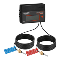
On the right-hand side of the back of the card (g. 1) there is
a key offering access to the technical manual.
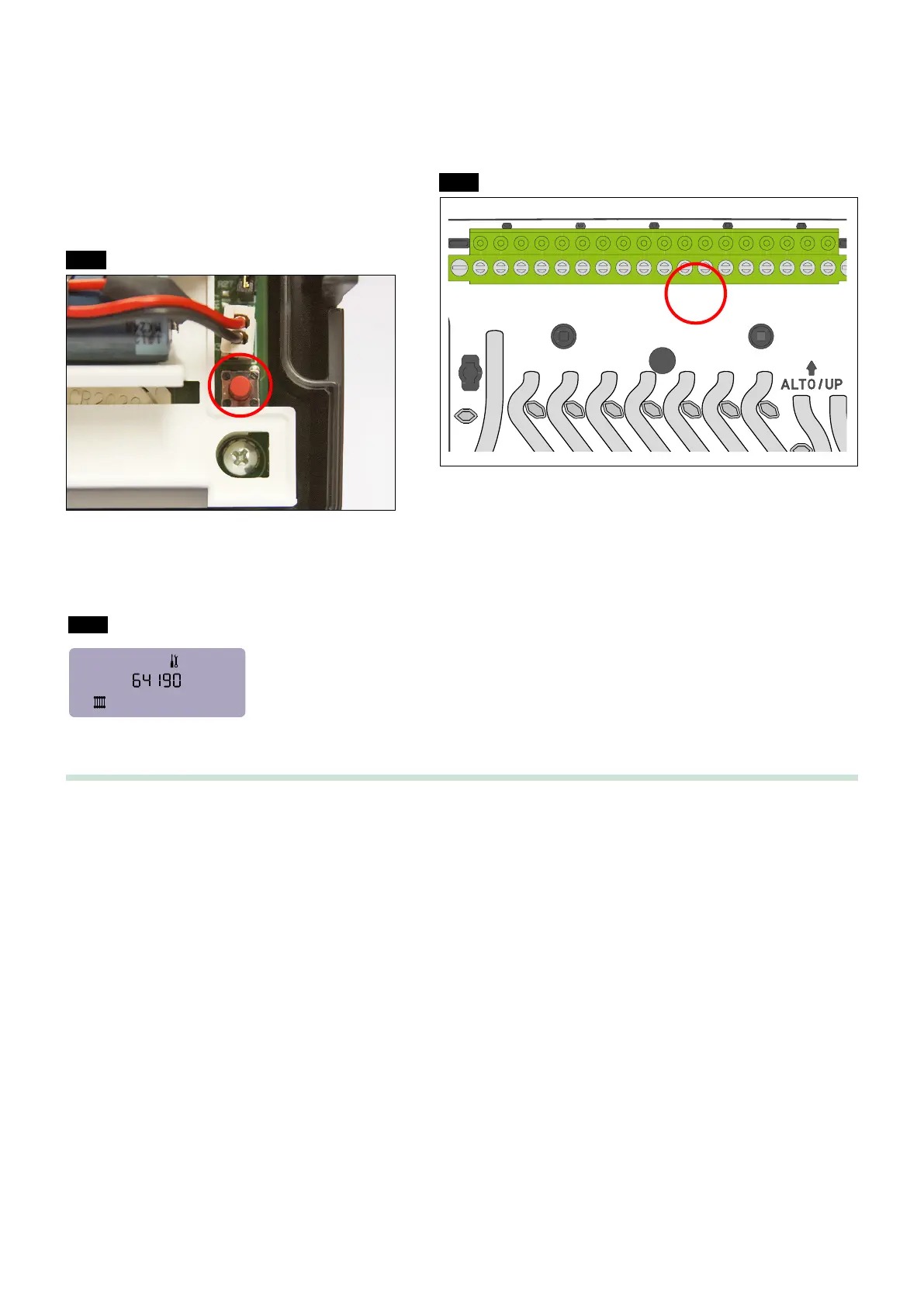
An input pulse can be simulated by connecting pins 11 - 12 (g. 3).
The maximum input pulse frequency is 1 Hz.
After pressing the key on the back of the card, pressing
the key on the front allows you to scroll through the various
screens.
The energy increases according to the following equation:
DE = κ⋅DT⋅DV⋅0,2777698⋅10
-3
[Wh]
The probes, which absolutely cannot be separated from the electronics circuit,
may be inserted in a thermostatic bath, observing the temperature range of
10–90 °C and taking account of a DT between 3–80 K
(g. 1)
(g. 2)
(g. 3)
ELECTRONICS BOX REAR PART
CABLE ROUTE
TEAR-PROOF CABLE CLIP
AA
AA
1234 56789101112131415161718
1234 56789101112131415161718
24 V (ac)
1234 56789101112131415161718
1234 5 6 7 8 910 11 12 13 14 15 16 17 18
RS485
1234 56789101112131415161718
Cooling units
1234 56789101112131415161718
1234 56789101112131415161718
digital input
A
B
Heating units
4
th
pulse input
3
rd
pulse input
pulse input
blue wire
white wire
Wh
8
κ = thermal coefcient [kJ/m
3
K]
DT = temperature change [K]
DV = volume change [ l ]
DV = N⋅P
where N = number of pulses
P = single pulse value per litre
Operating specications
1) In order to protect against spurious measurements or undesired metering, the metering control software makes the processing of consumption
subordinate to a specic ow temperature value (FT).
The heating metering cycle is activated for FT > 22 °C (factory setting).
The cooling units cycle is activated for FT < 15 °C (factory setting, with optional accessory code 755810).
On request, the setpoint values can be changed by technical personnel.
2) The software governing metering moreover has consumption processing subordinate to a
minimum temperature difference in order to provide further protection against spurious measurements or minimum metering due to
temperature tolerances. At the time of factory setting, a dead band of 0,4 K (factory setting) is therefore dened.
3) The software governing metering also requires installation of the ow rate meter on the return pipe.
On request and further to the action of technical personnel, the conguration setpoint can be adapted in order to install the meter on the ow
pipe.
 Loading...