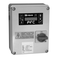
Electronic regulator for pumps
Elektronischer Pumpen für Druckschalter
IDROMAT
IDROMAT
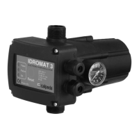
Installationsbeispiel - Installation example
1,2 bar
1.5 bar
P min 3.5 bar
2.2 bar
Max 22 m
P min 3 bar
P min 2.5 bar
Max 15 m
Max 10 m
.
.
..
.
..
.
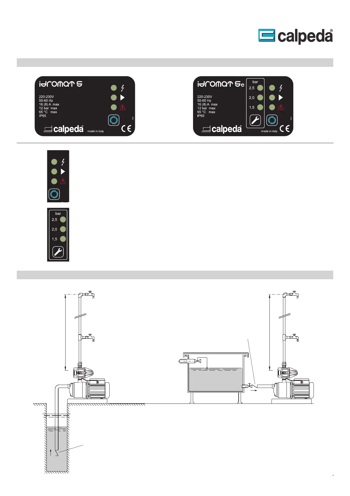
Control Panel
Die
die
Störung gestartet. neu Fehlerbeseitigung nach Pumpe die wird Reset-Taster dem Mit an.
eine zeigt untere die und ist Betrieb in Pumpe die ob LED mittlere die anliegt, Versorgungsspannung
ob an zeigt LED obere Die System. im Betriebszustände die über informieren LED - Anzeige drei
Status indications and system reset
The three leds give the information about the system operativity, the first led indicates the presence of
supply, the second led indicates if the pump is operating and the third led indicates if an alarm has
occurred in the system. The Reset button allows to manually restart the system when an alarm occur.
Statusanzeige System-Reset und
Die
werden.
verändert Tasten der Drücken durch kann Dieser an. Einschaltdruck eingestellten den zeigen LED
Programming of the re-start pressure
The display allows to visualize the re-start pressure of the system, the buttons allow to change the re-start
pressure value.
Einstellung 5e) (Idromat Einschaltdruckes des
4.93.096
IDROMAT 5-15: max 15 m
IDROMAT 5-12: max 12 m
IDROMAT 5-22: max 22 m
4.93.096/14
IDROMAT 5-15: max 15 m
IDROMAT 5-12: max 12 m
IDROMAT 5-22: max 22 m
I
Foot valve
Fußventil
Check valve
Rückschlagventil