9
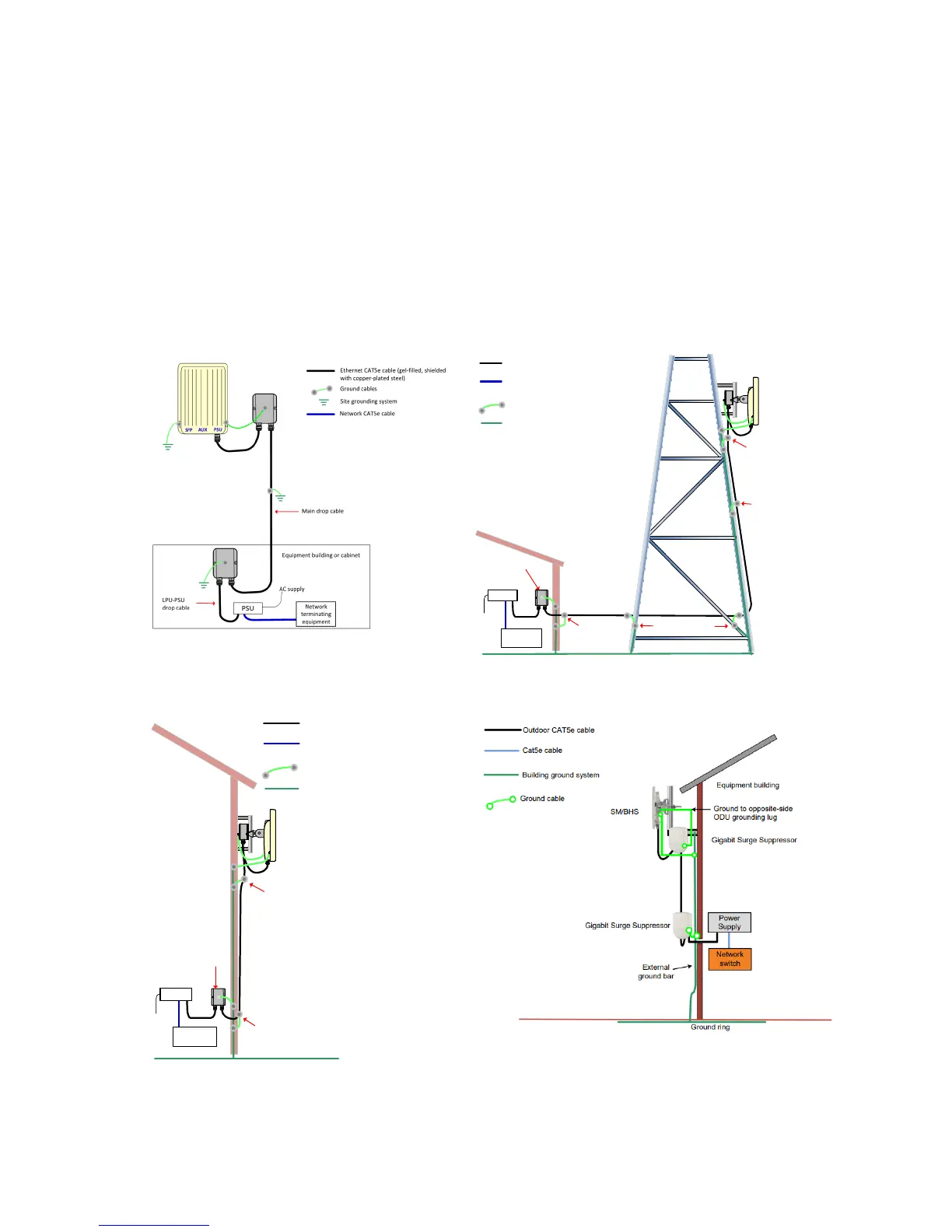
5. Typical Installation
In the simplest configuration (Figure 1), the data path from the network equipment (Ethernet interface), is
routed via a Power over Ethernet (PoE) injector (labelled ‘PSU’ in the figure) then via a copper cable to the
ODU (PSU port). Surge protection units should also be deployed as shown. A typical mast or tower
installation and wall installations is shown below (Figure 2, 3 & 4). Consult the user guide for detail of more
configurations.
Always site the radio equipment in a lightning protection zone:-
The equipment must be lower than the top of the tower or building or its lightning air terminal
The tower or building must be correctly grounded
Figure 1 Basic configuration Figure 2 Mast or tower installation
ODU
AC
supply
PSU
Network
equipment
ODU ground cables
Power over Ethernet CAT5e cabl e (gel-filled,
shielded with copper-plated steel)
Network CAT5e cabl e
Site grounding system
Bottom LPU
First point of contact
between drop cable
and tower
Tower ground bar
Ground ring
Intermediate
ground cable(s)
as req uir ed
Build ing
en try
Equipment building
or cabinet
ODU
PSU
Network
equipment
ODU ground cables
Site grounding system
Bottom LPU
Ground ring
First point of contact
between drop cable
an d w all
Building entry
Power over Ethernet CAT5e cable (gel-
filled, shielded with copper-pl at ed steel)
Network Cat5e cable
AC supply

 Loading...