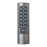
Standalone Keypad/Prox Access Control
• Remove the back cover from the keypad using the
supplied special screw driver
• Drill 2 holes on the wall for the Self tapping screws and
1 hole for the cable
• Put the supplied wall plugs into the two holes
• Attach the back cover rmly to the wall with the
2 Self tapping screws
• Thread the cable through the cable hole
• Attach the keypad to the back cover
6. Installation
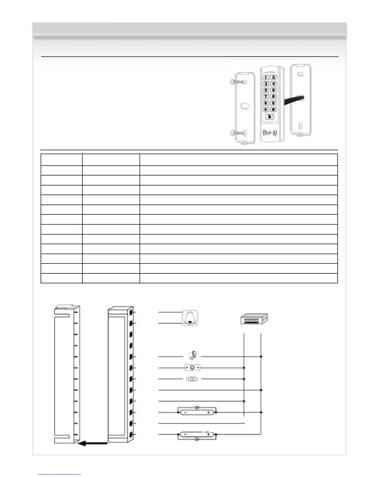
7. Wiring
Color Function Description
Pink BELL_A Doorbell
Pale Blue BELL_B Doorbell
Green D0 Wiegand output D0
White D1 Wiegand output D1
Grey ALARM Alarm negative (alarm positive connected 12 V+)
Yellow OPEN Exit button (the other end connected GND)
Brown D_IN Door Contact switch (the other end connected GND)
Red 12V+ 12V + DC Regulated Power Input
Black GND 12V - DC Regulated Power Input
Blue NO Relay Normally Open
Purple COM Relay Common
Orange NC Relay Normally Closed
Common power supply diagram:
Power supply
BELL_A PINK
D_IN BROWN
D0 GREEN
GND BLACK
ALARM GRAY
COM PURPLE
BELL_B PINK
+12V RED
D1 WHITE
NO BLUE
OPEN YELLOW
NC ORANGE
Bell
Connect
Alarm
Exibit Button
Door Contact
12V
+-
Fail Secure Lock
Fail Safe Lock
Page 3 of 8
+
 Loading...