Do you have a question about the CAMDEN Lazerpoint RF RX-92 and is the answer not in the manual?
Details the Camden Lazerpoint RF system, its models, and operational advantages for the automatic door industry.
Instructions for physically mounting the RX-92 receiver inside an automatic door header using screws or velcro.
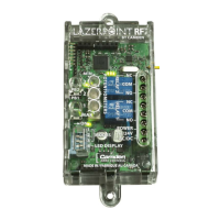
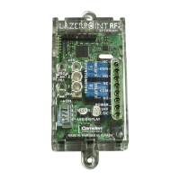
Guidance on wiring the RX-92 receiver to electric locks, operators, and power sources, including terminal descriptions.
Explains how to configure the RX-92 receiver's 6 operating modes using the 4-position dip switch.
Information on interpreting LED indicators for status and using dip switch 4 for signal strength testing.
Provides in-depth descriptions of the 6 operating modes for the RX-92 receiver, including dual outputs and latched modes.
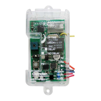
Details the connections required for the TX-9 wall switch ready transmitter, including battery installation.
Step-by-step procedure for programming TX-9 transmitters into the RX-92 receiver for various operating modes.
Instructions on using potentiometers to set delay-on-operate and delay-on-release times for the receiver's relays.
How to use DIP switch #4 to test and optimize transmitter/receiver placement for optimal signal reception.
Procedure to erase all learned transmitter codes from the RX-92 receiver's memory.
Information on adding daughterboards to extend RF compatibility to older technologies and frequencies.
Details on using the CM-RFCT cable tool for improved visibility of receiver status LEDs during installation.
Technical specifications for the Camden Lazerpoint TX-9 wall switch ready transmitter, including range and power.
Technical specifications for the Camden Lazerpoint RX-92 receiver, including voltage, current draw, and relay capabilities.
List and brief description of available accessories such as daughterboards and the CM-RFCT cable tool.
Outlines the 3-year limited warranty for Lazerpoint RF components and conditions for repair or replacement.
Compliance statements and technical specifications required by FCC and Industry Canada for radio transmitter operation.