14 - FA01650M4A - 10/2022 - © CAME S.p.A. -
Technical data
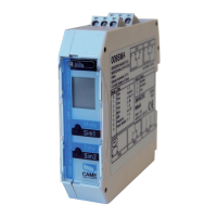
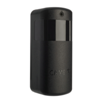
MODELS DXR20CAP DXR20CAM
Power supply (V - 50/60 Hz) 12 - 24 AC - DC 12 - 24 AC - DC
Operating temperature (°C) -20 ÷ +55 -20 ÷ +55
Protection rating (IP) 54 54
Storage temperature (°C)** -25 ÷ +70 -25 ÷ +70
Insulation class III III
Average life (cycles)** 100000 100000
(**) Before installing the product, keep it at room temperature where it has previously
been stored or transported at a very high or very low temperature.
(***) The average product life is a purely indicative estimate. It applies to compliant
usage, installation and maintenance conditions. It is also infl uenced by other factors,
such as climatic and environmental conditions.
C
Installation
1
Make a hole in the board box and thread the electrical cables through the hole.
Position the control board at the correct angle.
The maximum range is 180° horizontally and 10° vertically.
2
Secure in place using the screws for the rotating support and electronic board.
3
Attach the front cover.
Connections and settings
Use FROR cables 2 x 0.5 mm.
E
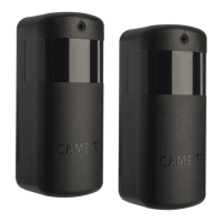
Connecting a pair of photocells.
G
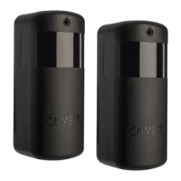
Connecting two pairs of photocells.
Set each pair of RX-TX photocells with its own address via the DIP-switches
(1-2-3).
H I
Connecting multiple pairs of photocells (max. 8).
Set each pair of RX-TX photocells with its own address via the DIP-switches
(1-2-3) and connect the SY terminals on the TX photocells together.
In a pair of photocells, all DIP-switches must be set to OFF, as shown in RX1
and TX1.
 Loading...