EasyManua.ls Logo

CAME ZC4 - User Manual

CAME ZC4
16 pages
Print Icon
To Next Page IconTo Next Page
Loading...
-1-
Documentazione
Tecnica
S34
rev. 2.1
02/2001
©
CAME
CANCELLI
AUTOMATICI
319S34
SCHEDA COMANDO
CONTROL BOARD
CARTE DE COMMANDE
STEUERPLATINE
TARJETA DE MANDO
SERIE Z |
Z SERIES
/ SÉRIE Z |
BAUREIHE Z |
SERIE Z
ZC4
CANCELLI AUTOMATICI
DESCRIZIONE
La scheda comando ZC4 è adatta al
comando di automazioni a 230V
monofase con potenza fino a 600W, in
particolare per i motoriduttori serie C e
F3000 per portoni industriali (scorrevoli,
a libro, sezionali etc.).
Va montata all’interno dei contenitori
S4339 oppure S4340, che sono dotati di
presa per il riciclo d’aria e di relativo
trasformatore (vedi ultima pagina).
La scheda deve essere alimentata a
230V (a.c.) sui morsetti L1 e L2, ed é
protetta in ingresso con due fusibili da
5A, mentre i dispositivi di comando a
bassa tensione (24V) sono protetti con
fusibile da 3,15A.
La potenza complessiva degli accessori
(24V) non deve superare i 20W.
Il tempo lavoro è fisso a 80 secondi.
SICUREZZA
Le fotocellule possono essere collegate
e predisposte per:
-
Riapertura
in fase di chiusura (2-C1), le
fotocellule rilevando un ostacolo
durante la fase di chiusura del cancello,
provocano l'inversione di marcia fino
alla completa apertura;
-
Stop totale
(1-2), arresto del cancello
con l'esclusione del ciclo di chiusura
automatica, per riprendere il movimento
del cancello, agire sulla pulsantiera o
sul radiocomando;
ACCESSORI COLLEGABILI
-
Elettroserratura
24V (11-ES);
ALTRE FUNZIONI
-
Chiusura automatica.
Il temporizzatore
di chiusura automatica si autoalimenta a
finecorsa in apertura. Il tempo prefissa-
to regolabile, è in ogni modo subordina-
to dall'intervento di eventuali accessori
di sicurezza e si esclude dopo un
intervento di "stop" o in mancanza
d'energia elettrica;
-
"Uomo presente"
. Funzionamento del
cancello mantenendo premuto il pulsan-
te (esclude la funzione del
radiocomando);
REGOLAZIONI
- Tempo chiusura automatica;
CARATTERISTICHE GENERALI
ITALIANO
ATTENZIONE : prima di
intervenire all'interno
dell'apparecchiatura,
togliere la tensione di
linea
FUS . CE NTR ALINA
T.C.A.
1 2
ZC4
QUADRO
COMANDO
FUSIBIL I LINEA
L1T L2T CT 0 2412
PROG
Question and Answer IconNeed help?

Do you have a question about the CAME ZC4 and is the answer not in the manual?

CAME ZC4 Specifications

General IconGeneral
BrandCAME
ModelZC4
CategoryController
LanguageEnglish

Summary

General Characteristics

Description

Details the ZC4 command board's suitability for 230V single-phase automations up to 600W.

Safety

Information regarding photocell connections for re-opening and total stop functions.

Key Functions and Adjustments

Covers other functions like auto-closing and adjustments for gate control.

Main Components

Component Identification

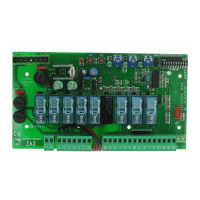
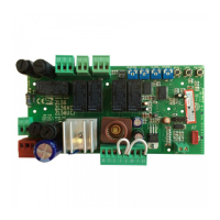
Lists and identifies the primary components of the ZC4 control board.

Terminal Block Connections

Details terminal block assignments for external connections and board functions.

Electrical Connections

Power Input and Motor Connections

Details connections for 230V AC power input and single-phase 230V AC motor.

Output and Accessory Connections

Explains connections for 230V AC output, 12V electric lock, and 24V accessories.

Signal Lamp Connections

Describes connections for signal lamps indicating gate status (open/closed).

Input Connections and Signals

Stop Pushbutton and Radio Control

Details connections for stop pushbuttons and radio/button control inputs.

Safety and Limit Switch Inputs

Explains connections for safety inputs (re-opening) and limit switch signals.

Antenna Connection

Describes the connection for the radio frequency antenna.

Dual Motor Installation

Coordinating Dual Motor Operation

Instructions for coordinating direction and settings for two combined motors.

Wiring for Combined Motors

Details the electrical connections required between two control panels for combined motors.

Radio Frequency Board Exclusion

Notes that the radio frequency board is not provided for combined installations.

Selections and Adjustments

Operator Presence and Auto-Closing Functions

Selection of "Operator Present" and automatic closing functions.

Automatic Closing Time Adjustment

Adjustment of automatic closing time using the T.C.A. trimmer (3-120 seconds).

Motor Torque Limiter

Adjusting Motor Torque

Instructions for adjusting motor torque by moving a specific faston.

Assembly Instructions

Assembling Hinges and Securing Housing

Steps for assembling hinges, inserting the housing, and securing it.

Securing the Control Panel Cover

Instructions for snapping the cover onto hinges and securing it with screws.

ABS Enclosures

Enclosure Models and Dimensions

Details dimensions for ABS enclosures 001S4339 and 001S4340.

Radio Control Installation

AF Board Insertion Procedure

Steps for inserting the AF board, encoding transmitters, and storing codes.

Transmitter Frequency Compatibility

Table listing compatible transmitter frequencies and corresponding AF boards.

Transmitter Encoding

ATOMO Transmitter Encoding

Instructions for encoding ATOMO series transmitters (AT01 - AT02).

TOP and TAM Transmitter Encoding

Instructions for encoding TOP (T432M, T312M, T434M, T314M) and TAM transmitters.

Code Storage

Storing Transmitter Codes

Procedure for storing transmitter codes using the PROG button and observing LED signals.

Related product manuals