EasyManua.ls Logo

CAME ZM2 - User Manual

CAME ZM2
32 pages
Print Icon
To Next Page IconTo Next Page
Loading...
-1-
Documentazione
Tecnica
S09
rev. 2.1
02/2001
©
CAME
CANCELLI
AUTOMATICI
319S09
SCHEDA COMANDO
CONTROL BOARD
CARTE DE COMMANDE
STEUERPLATINE
TARJETA DE MANDO
SERIE Z |
Z SERIES
/ SÉRIE Z |
BAUREIHE Z |
SERIE Z
ZM2
CANCELLI AUTOMATICI
CARATTERISTICHE GENERALI
Descrizione scheda
La scheda comando ZM2 è progettata
e costruita interamente dalla CAME
CANCELLI AUTOMATICI S.p.A.,
risponde alle vigenti norme UNI8612.
Adatta al comando di automazioni a
230V monofase con potenza fino a
600W, frequenza 50÷60Hz, in partico-
lare per i motoriduttori serie ATI,
FERNI, FROG, C, H, BX e BY (esclusi
BXE, BY1500) per cancelli e portoni
residenziali e industriali (battenti,
scorrevoli, a libro, sezionali, etc.).
Va montata all’interno dei contenitori in
ABS (S4339 o S4340) con grado di
protezione IP54, dotati di presa per il
riciclo d’aria e di relativo trasformatore.
Alimentata a 230V sui morsetti L1 e
L2, ed è protetta in ingresso con due
fusibili di linea da 5A, mentre i
dispositivi di comando a bassa tensio-
ne (24V) sono protetti con fusibile da
3.15A.
La potenza complessiva degli acces-
sori (24V) non deve superare i 20W.
ITALIANO
QUAD RO C OMAN DO
2
1
34
5
67
8910
O
N
FUSIBILI
LINEA 5A
ZM2
CH2
CH1
AF
FUS.
CENTR.
3.15A
T.L.
T.C.A.
TR2M.
2
1
Question and Answer IconNeed help?

Do you have a question about the CAME ZM2 and is the answer not in the manual?

CAME ZM2 Specifications

General IconGeneral
BrandCAME
ModelZM2
CategoryController
LanguageEnglish

Summary

Board Description

Safety Features

Protects against obstacles and ensures safe operation of automated gates.

Connected Accessories

Details compatible accessories like signal lamps and electric locks.

Selectable Functions

Configuration options for gate operation modes and safety features.

Main Components and Connections

Component Identification

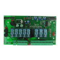
Lists and identifies key components like terminals, fuses, and controls.

Electrical Wiring Guide

Comprehensive guide for connecting power, motors, safety devices, and accessories.

Safety System Configuration and Testing

DIP-Switch Settings

Configuration options via 10-way and 2-way DIP switches.

Photocell Function Test

Procedure for verifying the proper operation of photocell safety devices.

Operation Adjustments

Trimmer Adjustments

Adjusting operating time, auto-close time, and motor 2 delay.

Installation and Transmitter Setup

Assembly Instructions

Step-by-step guide for installing the control unit housing.

Radio Control Installation

Procedures for installing the AF card and configuring radio transmitters.

Transmitter Encoding and Code Storage

Methods for encoding transmitters and storing codes on the control board.

Related product manuals