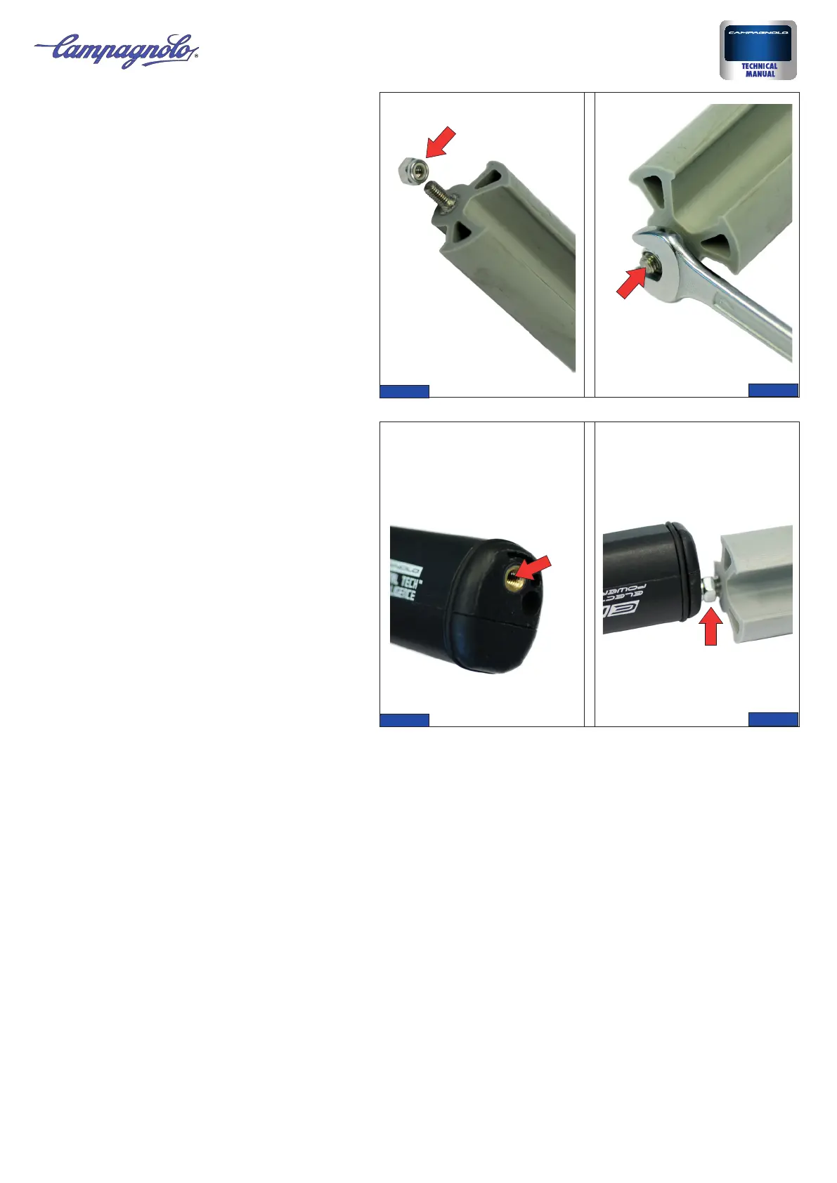
5) Screw the pivot onto the threaded seat at the end
of the power unit (Fig. 7) until it comes into contact
with the nut (Fig. 8).
3) Ensure that the elastic support is compatible with
the seat support tube you have.
4) Tighten the nut (Fig. 5) provided with the support
all the way on the threaded pivot of the support (Fig.
6).
6) Bringing the seat support tube alongside the column tube, in the minimum seat support tube insertion position ensure that
the length of the power unit’s 4 cables is sufficient as shown.
Ensure that the 3 male connectors of the rear derailleur cables (green), front derailleur (yellow) and interface (red) can come
out of the frame holes in order to be connected to the respective female connectors of the components being connected.
Ensure that the connector for recharging the power unit can be positioned in the pre-bored hole on the frame.
If the cables are not long enough procure adequate extensions (see the Tools and accessories table).
• For the rear derailleur (55 cm), front derailleur (55 cm) and interface (135 cm) cables the “Cable extension for EPS PU instal-
lation under seat” kit is available (Super Record/Record or Chorus/Athena version)
• For the single interface cable (25 cm) the “Cable extension for EPS PU under BB installation” is available (Super Record/
Record or Chorus/Athena version)
• For the recharge connector cable (50 cm) the “Recharge extension cable for Power Unit EPS V2” is available
Note
Remember that if the extensions are not used, once the power unit is installed you may not be able to remove the seat support
tube from the column tube. The crankset may need to be disassembled and the power unit of various components may need
to be disconnected.
EPS
3Rev. 01 /10-2016
8
7
5
6
 Loading...