5 6
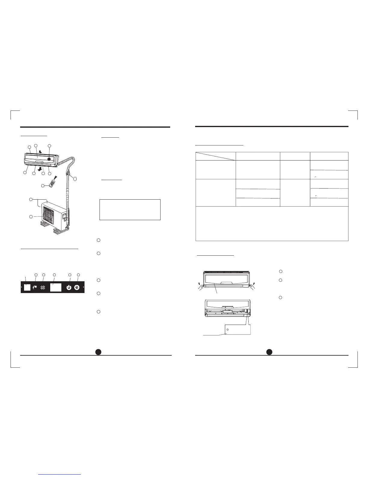
Parts names
Outdoor unit
OPERATING INSTRUCTIONS
Indoor unit
NOTE:
All the pictures in this manual are for
explanation purpose only. Your air
conditioner may be slightly different.
The actual shape shall prevail.
4
3
5
2
6
1
8
10
11
9
7
1. Front panel
2. Air inlet
3. Air filter
4. Air outlet
5.
6.
7. Display panel
8. Remote controller
Horizontal air flow grille
Vertical air flow louver
9. Connecting pipe, drain hose
10. Air inlet (side and rear)
11. Air outlet
Indoor unit
Outdoor unit
Indicator Lights on Display panel
The display panel on the indoor unit
would look like one of the following:
AUTO indicator:
DEFROST Indicator
DIGITAL DISPLAY:
indicator:
TIMER indicator:
This indicator illuminates when the air
conditioner is in AUTO operation.
This indicator illuminates when the air
conditioner starts defrosting automatically
or when the warm air control feature is
activated in heating operation.
Displays the current setting temperature
when the air conditioner is in operation.
The indicator flashes once every second
after power is on and illuminates when the
air conditioner is in operation.
The indicator illuminates when TIMER is
set ON/OFF.
(For cooling& heating model only):
OPERATION
1
2
3
4
5
11
Signal
receptor
(C
)
。
T
E
M
P
A
U
T
O
C
O
O
L
D
R
Y
H
E
A
T
FA
N
H
I
G
H
M
E
D
L
O
W
MODE
FAN SP
EED
T
I
M
E
R
O
N
S
L
E
E
P
O
N
/
O
F
F
T
I
M
E
R
O
F
F
A
I
R
D
I
R
E
C
T
I
O
N
R
E
S
E
T
L
O
C
K
S
E
T
T
E
M
P
E
R
A
T
U
R
E
S
W
I
N
G
L
E
D
D
I
S
P
L
A
Y
T
U
R
B
O
auto
2 3
4
5
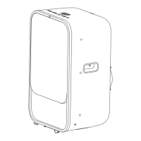
Manul operation can be used temporarily in case the remote controller is disable or
maintenance necessary.
OPERATING INSTRUCTIONS
Manual operation
Manual control
button
Panel
AUTO/COOL
NOTE: This manual does not include Remote Controller Operations, see the
<<Remote Controller Instruction>> packed with the unit for details.
Operating temperature
Open and lift the front panel up to an angle
until it remains fixed with a clicking sound.
Push the button until the AUTO indicator
is lit, the unit will work in forced AUTO
mode (the default setting temperature
is 24 ).
Close the panel firmly to its original
position.
℃
Once you push the manual button, the
operation mode is shifted in an order as:
AUTO, COOL, OFF.
This is used for testing purposes only.
To restore the remote controller operation,
use the remote controller directly.
CAUTION:
1
3
2
●
●
●
Mode
Cooling operation
Heating operation
Drying operation
Temperature
1. If air conditioner is used outside of the above conditions, certain safety protection features may
come into operation and cause the unit to function abnormally.
2. Room relative humidity less than 80%. If the air conditioner operates in excess of this figure, the
surface of the air conditioner may attract condensation. Please sets the vertical air flow louver to its
maximum angle (vertically to the floor), and set HIGH fan mode.
3. Optimum performance will be achieved within these operating temperature.
Room temperature
Outdoor temperature
17 C 32 C
。。
18 C 43 C
。。
0C 30C
-7 C 24 C
。。
。。
11 C~43 C
OO
(<21000Btu/h models)
10 C~32 C
OO
(<21000Btu/h models)
17 C~32 C
OO
(>21000Btu/h models)
18 C~43 C
OO
(>21000Btu/h models)
~
~
~
( -5 C 43 C:For the models with
low temperature cooling system)
。。
~
~
(21 C 52 C:For special tropical
models
。。
~
21 C 52 C
(For special tropical models)
。。
~
NOTE: