1
Single wire pan support
2
Ring for glass lid
3
Glass lid
4
Hinge for glass lid
5
Plastic cap
6
Silent block for resting lid
7
Fixing screws cap
8
Fixing screws for moulding
9
CE label
10
Metal moulding
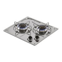
11
SR burner cup with injector nozzle
12
Gas capillary pipe for SR burner
13
Gas cock with safety valve
14
AUX burner cup with injector nozzle
15
Gas capillary pipe for AUX burner
16
Main gas train
17
SR burner spreader
18
SR burner cap
19
AUX burner spreader
20
AUX burner cap
21
Burner caps and spreaders fixing screws
22
Rubber feet/bushings for pan support
23
Knob for gas cock
24
Gas cock fixing nut
25
Control panel sticker
26
Piezoelectric igniter
27
Lighting glow plug with fixing clip
28
Thermocouple with nut
29
Burner stud bolt