Do you have a question about the CanadianSolar CS7N-MS and is the answer not in the manual?
Important safety instructions for installation, handling, and electrical safety on site.
Obtain site approvals, check building codes, and ensure system compatibility with authorities.
Compliance with UL 1703 and National Electrical Code for grounding in North America and other regions.
Detailed steps and components for proper module grounding using specific hardware.
Adherence to safety, accident prevention, and applicable local codes and requirements.
Compliance with UL 1703/61730 and IEC 61215 for module mounting and support structure design.
Information on approved mounting methods and warranty implications for non-standard installations.
Detailed instructions for bolting modules to supporting structures, including hardware and torque specifications.
Table listing approved bolting methods and load capacities for different module types.
Specific measures for clamp installation, overlap, thickness, and material requirements.
Table detailing maximum mechanical loads for four-clamp configurations on long side frames.
Table detailing maximum mechanical loads for four-clamp configurations on short side frames.
Table detailing maximum mechanical loads for four-clamp configurations on long side frames parallel to rails.
Table detailing maximum mechanical loads for two-clamp configurations.
Table detailing maximum mechanical loads for four-clamp configurations on short side frames.
Table detailing maximum mechanical loads for four-clamp configurations on short side frames.
Table detailing maximum mechanical loads for four-clamp configurations with an additional support bar.
Table detailing maximum mechanical loads for six-clamp configurations on long side frames.
| Brand | CanadianSolar |
|---|---|
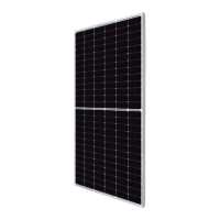
| Model | CS7N-MS |
| Category | Solar panel |
| Language | English |