Do you have a question about the CanadianSolar CSI-50K-T400GL03-E and is the answer not in the manual?
Details the function of CSI Grid-Tied PV Inverters converting DC to AC power.
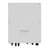
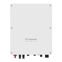
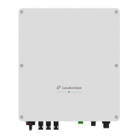
Lists included parts and instructions for receiving and storing the inverter.
Provides instructions for storing the inverter safely and under suitable environmental conditions.
Explains various safety symbols used in the manual and their meanings.
Provides essential safety guidelines for inverter installation and use.
Specifies requirements for inverter installation and intended use.
Describes built-in protective circuitry and control features like Anti-Islanding Protection.
Outlines environmental factors to consider when selecting an installation location.
Provides detailed criteria for choosing an appropriate installation site for the inverter.
Covers additional factors like technical data, vertical mounting, and avoiding sunlight.
Provides instructions on how to safely handle and move the inverter during installation.
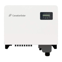
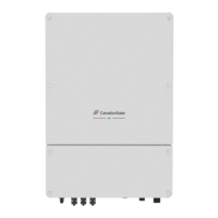
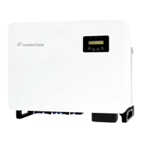
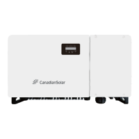
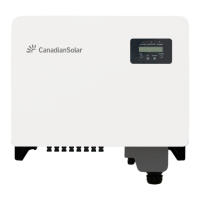
Details how to mount the inverter, including wall and rack mounting options.
Step-by-step guide for securely mounting the inverter to a wall.
Instructions for mounting the inverter onto a rack system.
Explains how to make all electrical connections to the inverter.
Details the procedures for proper grounding of the inverter.
Step-by-step guide for connecting the DC input from the PV array.
Instructions for connecting the inverter to the utility grid.
Details how to connect datalogging sticks for inverter monitoring.
Explains connecting a datalogging stick to the 4-pin COM port for remote monitoring.
Describes how to connect for monitoring multiple inverters using daisy chain.
Details connection for Demand Response Modes (DRM) and logic interface.
Explains the PLC communication option for data transfer.
Describes connecting a smart meter for export power management and consumption monitoring.
Explains how to select and verify the correct grid standard for the installation country.
Provides steps for changing the inverter's grid standard setting.
Guides on setting a custom grid configuration for specific needs.
Lists critical checks to perform before operating the inverter.
Details how to verify the DC connections are secure and correct.
Details how to verify the AC connections are secure and correct.
Covers checking DC configuration, including VOC, polarity, and leakage.
Covers checking AC configuration, including Vac, frequency, and phase rotation.
Step-by-step guide on how to safely start up the inverter.
Step-by-step guide on how to safely shut down the inverter.
Overview of main menu, information access, and screen locking.
Covers general settings, time, and address configuration.
Accessing advanced diagnostic and status information requiring technician access.
Checking daily, monthly, and yearly energy generation data.
Viewing daily records, communication data, and warning messages.
Accessing advanced settings like standard selection and power control.
Configuring 24H switch, energy clearing, password reset, and power control.
Includes energy calibration, special settings, and STD mode settings.
Enabling DRM/Logic interface, restoring settings, and HMI updates.
Setting internal EPM, backflow power limits, and fail-safe options.
Configuring backflow work modes, external EPM, and HMI restarts.
Performing fan tests, DSP updates, compensation, and I/V curve scans.
Setting parameters for I/V curve scanning and analyzing results.
Enabling and managing the Arc Fault Circuit Interrupter (AFCI) function.
Details the optional module to recover PID effect during the night.
Provides instructions for cleaning or replacing the inverter's cooling fans.
Lists common alarm messages, failure descriptions, and recommended solutions.
States compliance with REACH regulation regarding substances of concern.
Declares conformity with CE, Low Voltage, EMC, and RoHS directives.
Checklist items covering site preparation, unpacking, mounting, and connections.
Checklist items for final power-up, parameter settings, and operational verification.
| Model | CSI-50K-T400GL03-E |
|---|---|
| Rated Output Power | 50 kW |
| Max. DC Voltage | 1100 V |
| Start Voltage | 250 V |
| Input Voltage Range | 200 V - 1000 V |
| Max. Input Current per MPPT | 30 A |
| Number of DC Inputs per MPPT | 2 |
| Max. AC Current | 80 A |
| Rated AC Voltage | 400 V |
| Nominal Frequency | 50 Hz / 60 Hz |
| MPPT Efficiency | 99.5% |
| Total Harmonic Distortion (THD) | <3% |
| DC Switch | Yes |
| Protection Class | IP65 |
| Operating Temperature Range | -25°C to +60°C |
| Weight | 65 kg |
| Max. DC Power | 75000 W |
| MPPT Range | 200 V - 850 V |
| Max. AC Power | 55000 VA |
| AC Output Voltage Range | 320 V - 480 V |
| AC Voltage Range | 320 V - 480 V |
| Power Factor | 0.8 leading - 0.8 lagging |
| Type | Three-phase grid-tied inverter |
| Cooling | Smart Air Cooling |