5
Detector reset (L+ when programmed for ID)
Some detectors require the removal of power to reset (e.g. Viper Plus® or Smoke
detectors). The L+ terminal can be programmed to be used as an 'ID' output using
option 7-4. The L+ terminal should then be used as the negative supply for these
devices. The positive supply should be taken from the AUX +.
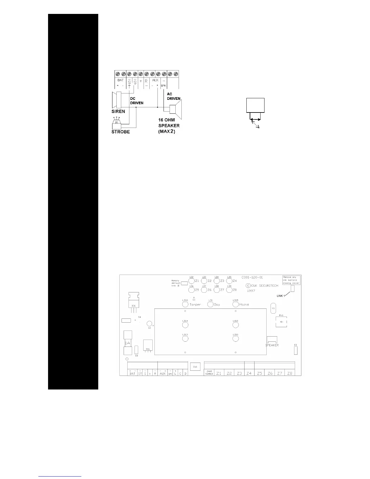
Internal Sounders, Speakers, Strobe and Keyswitch Wiring.
** DIAGRAM A **
A maximum of two 16 ohm speakers may be
fitted in parallel.
External Sounder & Strobe.
Connection for external sounder and strobe are shown in diagram A. Please note
sounder trigger is applied negative. (Negative ring).
ST- Strobe switched negative trigger.
S - Sounder switched negative trigger
+ Sounder hold off/strobe positive supply.
- Sounder hold off supply & sounder tamper feed (negative)
-R Sounder tamper return. (negative)
AUX DC - Detector power.
The auxiliary power is provided from connections marked 'AUX'. This is to provide
the 12 V supply for detectors e.g. movement or glassbreak detectors. The auxiliary
power output is rated at 500 mA max. (12 VCD nominal). See diagram B
** DIAGRAM B **
DETECTOR
RESET
INTERNAL
DEVICES
EXTERNAL
DEVICES
AUXILIARY
POWER
BASIC BOARD
LAYOUT
Keyswitch Connections
Open = ON
Closed = OFF
Z8 only
OFF
ON