13
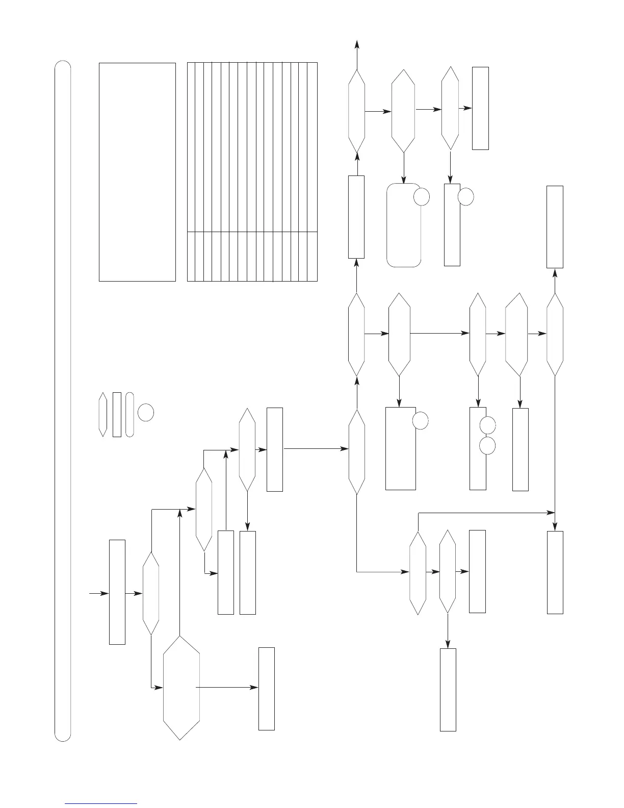
FAULT FINDING CHART Part 1
Switch on the main electrical supply
Does the green LED
alight ?
- Check mains electrical
connection
- Check internal fuses
- Check connection between
the 2 PCBs
Replace control PCB or
display PCB
Replace control PCB
Switch heating ON
Release pump rotor
Replace pump
Replace fan assembly
- Check heating flow switch
- Check the main heat exchanger.
They could be fully scaled.
Does the red LED
light ?
Does the display
show a - XX code ?
Does the fan run ?
Check heating fl
ow rate in
the circuit
Check voltage on the
fan
Check the 24 V at the
transformer
Press the reset button
Please refer to the list of error
codes and solve the problem
Check that the pump
spins freely
Check voltage in the
pump electrical box
Replace control PCB
Could you see the
spark generation?
Does the spark
generator energize ?
Does the -24 error
display ?
Replace spark generator or
ignition electrods assembly
Replace transformer or the rele-
vant fuse
Wait for 1 minute if the error
code 24 still display.
- check the connection fan or
replace the fan
Yes
Yes
Yes
Yes
Yes
No
No
No
No
Ok
No
Ok
Replace heating thermistor
Check heating
thermistor
Ok
No
No
No
No
Yes
Yes
Yes
No
No
No
Ok
Ok
Ok
Ok
means a test or a choice
means an action
means a group of actions
error code displayed
PLEASE CHECK THE FOLLOWING POINTS CAREFULLY BEFORE
GOING THROUGH THE FAULT FINDING CHART
-Gas pressure
-Electric mains
-Minimum water pressure in the heating circuit (over 0.8 bar)
-All isolating valves have been opened
-Boiler air vented
-Check that the heating filter is clear.
- Remove the front panel of the sealed chamber
-7
Does the pump run ?
No
-7
-11
-12
Ok
Ok
No
No
-3
Wait for 4 seconds
Error code Description
1 Overheating LockOut
3 No flame detection
5 Anti-frost mode on
6 Anti-frost mode on
7 No water circulation
8 Faulty water circulation in the primary circuit
11 Central heating thermistor faulty, Opened circuit
12 Central heating thermistor faulty, Short circuit
18 Ignition test
20 Faulty connexion
23 Low speed fan
24 Faulty control functionning fan
31 Error communication with EEPROM
32 Error communication with the main PCB
-24