12
55.. CCOOMMMMIISSSSIIOONNIINNGG
55..11..11..
Open the gas and water service cocks benea-
th the appliance, purge the gas supply (BS 6891).
Turn on an adjacent tap and purge the water side of
the installation.
Test for water soundess at all appliance and exter-
nal pipework connections;
Switch on electrical supply, fan will run at low
speed.
55..11..22..
Remove Protective Film from casing before
use.
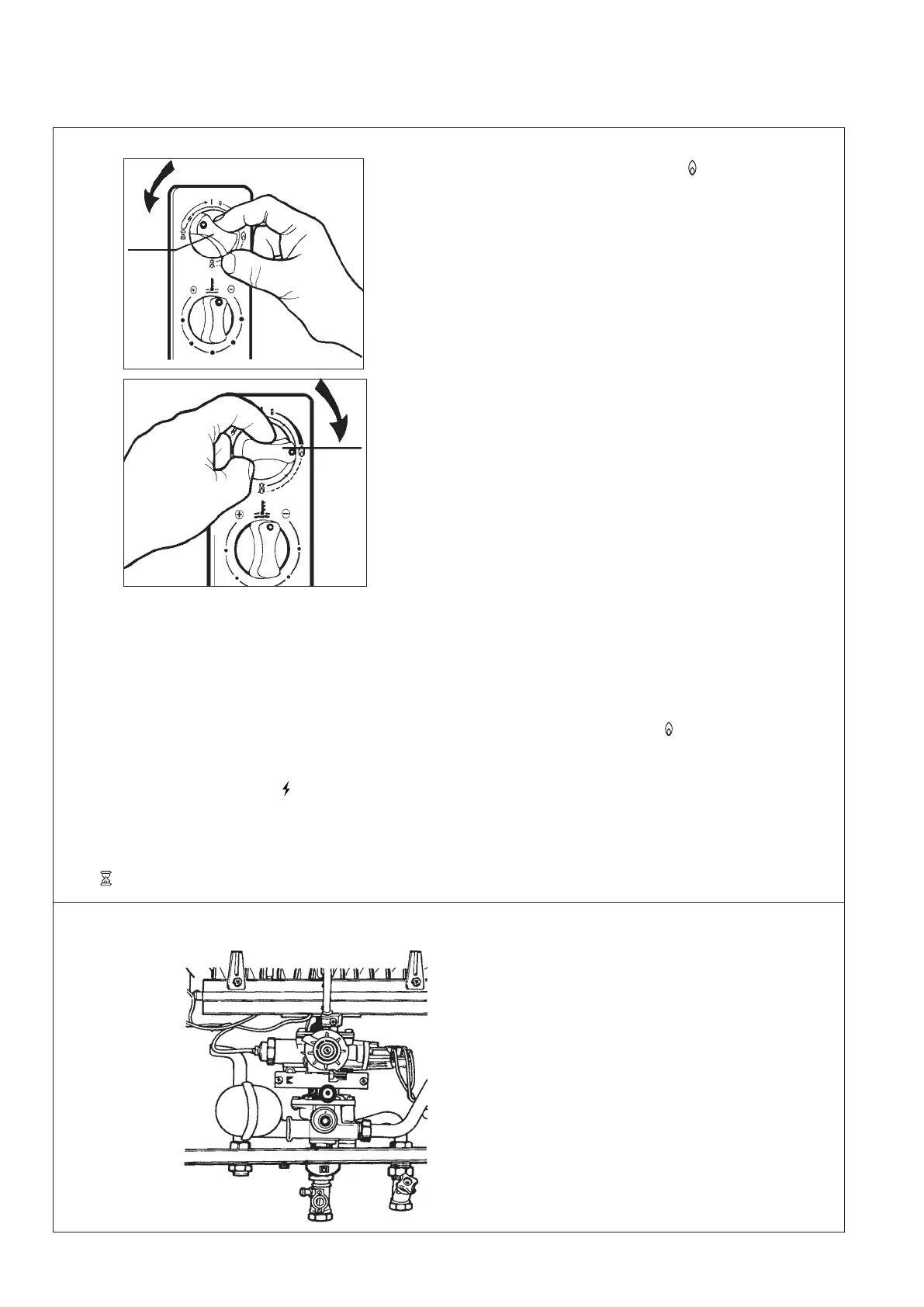
55..11..33.. TToo lliigghhtt tthhee ppiilloott
, temporality fit the gas
control knob (A) and light the pilot by turning the
knob 90° anti-clockwise in « » horizontal position
(see fig. 13). It may be necessary to pur
ge the pilot
gas supply, if so, wait a few minutes, return the gas
control knob to the «
I» vertical position and repeat.
(The pilot supply will only pur
ge when the gas
contr
ol knob has been tur
ned 90° anti-clockwise in
« » horizontal position).
55..11..44..
W
hen the pilot is lit, turn the control knob
(A) fully clockwise to the « » position as
s
hown in the diagram (see fig. 14). Test for gas
soundness using leak detection fluid on all gas
connections.
55..11..55.. CChheecckk tthhee ooppeerraattiioonn ooff tthhee ffllaammee
ssuuppeerrvviissiioonn ddeevviiccee
by blowing out the pilot
light, the flow of gas to the pilot will cease
and the thermoelectric valve should drop out
with an audible «click» within approximately
30 seconds.
55..11..66..
Re-light pilot and check gas pressures
see Section 5.2.
55..11..77..
Remove gas control knob (A).
55..11..88..
Switch off electrical supply.
55..11..99..
Fit front case by location bottom first
and ensuring top of case locates over brac-
ket. Secure with 4 screws and washers pre-
viously removed.
- The centre screw and plastic washer retains
the fascia mounting bracket.
- Replace the control fascia plate by sliding
down onto the support bracket.
- Fit bottom trim by sliding onto rails.
- Fit the gas control knob (A) and the tempe-
rature selector knob (B). The temperature
selector knob should be pushed onto the
spline until it locates. Turn fully clockwise
to (+), reposition knob as required, so that
indicator dot is opposite the (+) sign.
55..11..1100..
Switch on electricial supply.
- Light the pilot and turn gas control knob (A)
fully clockwise to the « » main gas posi-
tion.
55..11..1111..
Perform operations as detailed in
sections 5.3 to 5.7.
55..11 PPuuttttiinngg iinnttoo SSeerrvviiccee
55..22 GGaass PPrreessssuurree
FFiigg.. 1133
FFiigg.. 1144
FFiigg.. 1155
- T
urn on an adjacent hot water draw off, the
appliance will now light and the fan will
change to high speed.
- Check bur
ner setting pr
essur
e at test point A
see Section 1.3 technical data (see fig. 15).
- If the burner setting pressure is not correct,
check that the pr
essure at the gas service
cock, test point B is 20 mbar (8. in.
w
.g.)
with the appliance operating. If the inlet
pressure is not correct, check for any pos-
sible blockage or restriction in the pipe-
work to the appliance. If the inlet supply
pr
essur
e cannot be cor
rected contact your
local gas r
egion. The heat input to the
appliance is pre-set and non-ajustable.
A
B
A
A
 Loading...