13
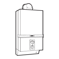
55..33 SSllooww IIggnniittiioonn
-
Check burner ignition which should be smooth and
quiet (not explosive).
- If slow ignition requires adjustment proceed as in
Section 6.1 to remove front case.
- Adjust slow ignition device A (see fig. 16) 1/4 turn
a
t a time. Refit front case and recheck operation.
NNOOTTEE ::
Turning screw A clockwise delays ignition.
55..44 MMiiccrroosswwiittcchh
NNOOTTEE ::
During Commisionning it is important that the correct operation of the microswitch on the side of the
gas section is checked.
Whilst the microswitch is factory set, it may require adjustment. When the appliance is at rest the fan runs conti-
nuously at low speed. Check operation as follows - set temperature selector to - then open draw-off. The fan
should now come to high speed before the burner ignites. On closing draw-off, the burner should extinguish
before the fan resumes at low speed. If fan/burner operational sequence is NOT as described see Section 7.13.
55..55 TThhee PPrreessssuurree SSwwiittcchh
Check the operation of the pressure switch as follows : Open draw off, fan comes to high speed and the bur-
ner ignites. Close draw off, burner extinguishes and when fan resumes at low speed listen for the “click” as the
relay changes over.This should be followed within 15 seconds by a lighter “click” as the pressure switck changes
over. If the time separation is greater than 15 seconds or if the pilot extinguishes it suggests that the pressure
switch is incorrectly set. (See Section 7.11).
55..66 TThheerrmmooeelleeccttrriicc CCiirrccuuiitt
The Thermoelectric Circuit is fitted with an interrupter so that if the air flow is not proved on high speed the cir-
cuit is incomplete and the flame super
vision device will operate. In the case of inter
mittant pilot faillur
e or per
-
manent pilot failure the termocouple circuit can be checked with a British Gas Multimeter or suitable Millivolt
Meter to determine if the pilot failure is due to poor thermoucouple output, high resistance through Relay-1
contact or faulty ther
moelectric valve. (See Section 2.9, fig. 1).
The ther
mocouple output measur
ed at the Printed Cir
cuit Board terminals should be greater than 12 millivolts.
The millivoltage dr
op through the relay (i.e. terminal to terminal) should not be gr
eater than 4 millivolts.
55..77 HHaannddiinngg OOvveerr
Hand all instructions to the user or purchaser and instruct in the correct and safe operation of the appliance.
Explain to the user or purchaser that if the appliance is not used for long periods it is recommended that the
appliance is drained, this is particulary important during the winter months (see servicing instructions for pro-
cedure to drain appliance).
Finally, advice the user or purchaser that, for continued efficient and safe operation of the appliance it is impor-
tant that servicing is carried out annually to the manufactures recomendations by a C.O.R.G.I. registered person.
FFiigg.. 1166
A
 Loading...