14
66.. RROOUUTTIINNEE SSEERRVVIICCIINNGG
T
o ensure continued efficient and sale operation of the appliance it is recommended that it is checked and serviced
as necessary at regular intervals. The frequency of servicing will depend upon the particular installation, condition
and usage, but in general once a year should be adequate.
It is the law that any service work must be carried out by a competant person, such as British Gas, other C.O.R.G.I.
registered personnel or your local Chaffoteaux Service Centre in accordance with the Gas Safety (Installation and
Use Regulations). This routine service will normally be confined to :
1) Cleaning the burner.`
2) Cleaning the heat exchanger.
3) Checking the gas controls.
4) Cleaning water filter, and water governor.
5) Check diaphragm and replace every three years.
The following schedules are recommended :
a) Check the function of appliance, burner pressure, gas flow rate and soundness.
b) Observe flame picture and undertake combusion test.
c) Check clean or replace components as necessary.
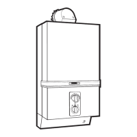
66..11 FFrroonntt CCaassiinngg
TToo rreemmoovvee ::
- Pull off gas control and temperature selector knobs.
- Remove controls facia plate by sliding upwards.
- Remove the four fixing scr
ews which secure the front
case (top, bottom and centre) taking care not to lose
facia retaining bracket and washers.
- Remove to front case by lifting off the to locating lugs
and pulling forward to clear the water section at the
base of the appliance.
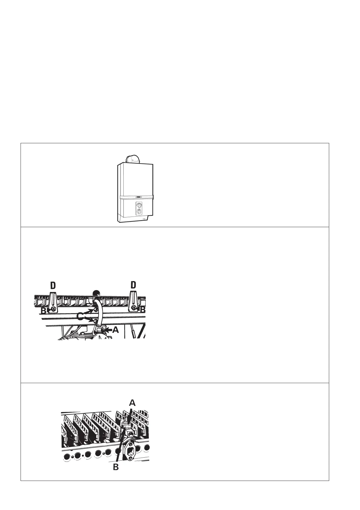
66..22 BBuurrnneerr
- Remove the combustion chamber front panel as fol-
lows.
- Remove two threaded screws which secure the front
panel of the combustion chamber skirt to the flue
hood (A) Section 6.4.
- Remove three self-tapping screws on either side of
combustion chamber skirt (B) Section 6.4.
- Unscrew the pilot tube clamping screw (A) and remo-
ve the clamp and screw and pilot tube.
- Remove the burner manifold by unscrewing the two
screws and washers (C) (see fig. 17).
- Withdraw the burner head assembly taking care not
to damage the pilot burner/electrode assembly or the
ignition lead.
- The burner head should be turned upside down and
cleaned by brushing.
- Replace in r
eser
ve or
der making sur
e that the gasket
between the bur
ner manifold and gas section is in
place and is in good condition. If necessary replace
gasket and ensure that the burner head assembly is
correctly located on the two spigots at the rear.
66..33 PPiilloott
- Remove combustion chamber front panel, burner
and pilot tube as in 6.2. if not already removed.
- Blow through the tube to remove any dust.
- Remove screw securing spark electr
ode.
Lift out of
f
“D” slot and ease to one side.
- Unscrew the knurled pilot burner outer ring (A).
- Remove flame retention gauze (see fig. 18).
- Unscrew the pilot body (B) with a 15 mm spanner.
Clean by br
ushing and blowing.
DO NOT CLEAN HOLES WITH A WIRE.
- Re-assemble in reverse order ensuring pilot body is
screwed down tightly.
FFiigg.. 1177
FFiigg.. 1188
 Loading...