15
66..44 HHeeaattiinngg BBooddyy
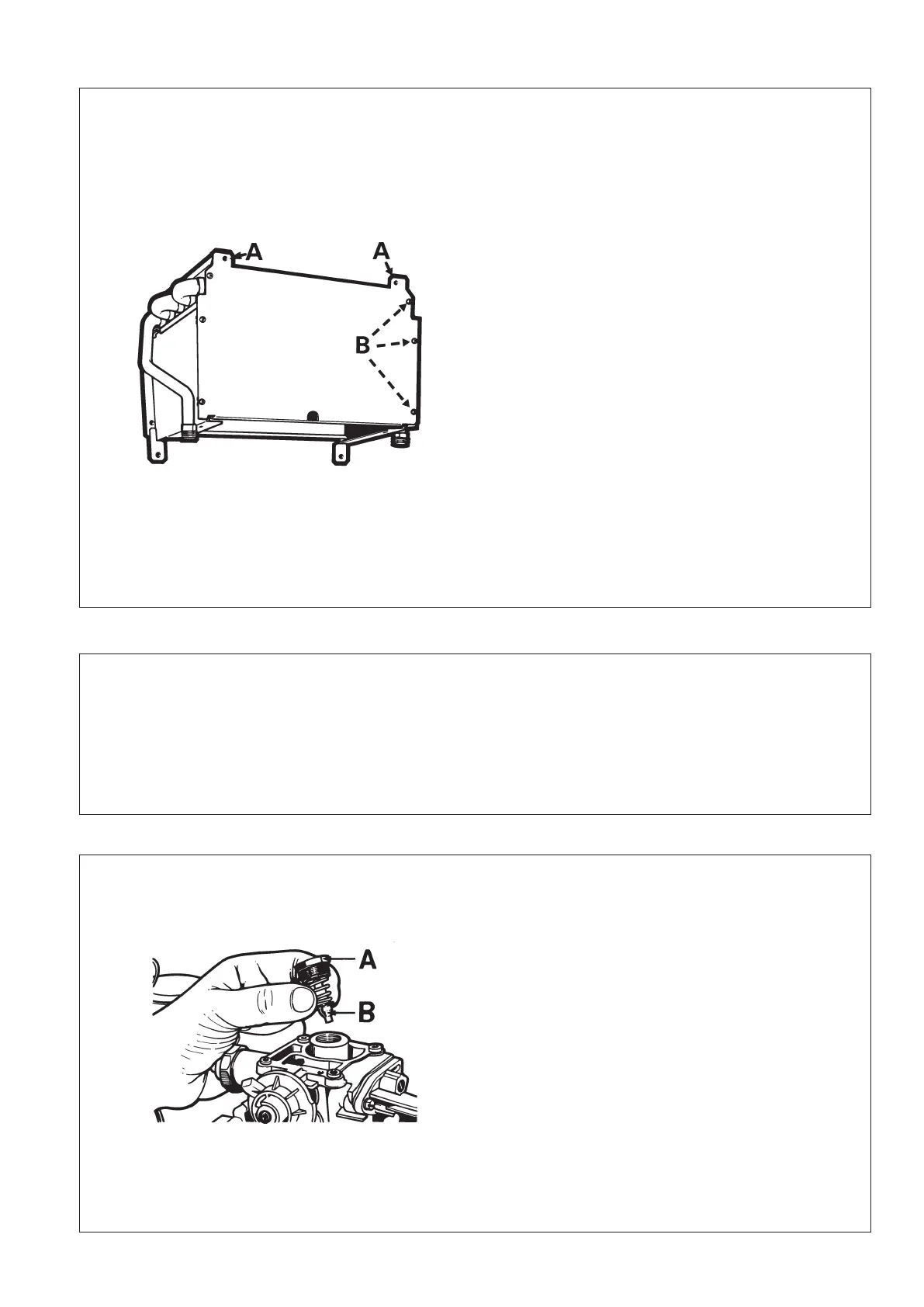
aa)) TThhee hheeaatt eexxcchhaannggeerr ccaann bbee eexxaammiinneedd iinn ppoossiittiioonn ::
(see fig. 19)
- Remove combustion chamber front panel as in
Section 6.2. if not already removed. Prior to clea-
ning the heat exchanger adequate precaution
should be taken to protect the pilot burner/gas
valve assembly to prevent the ingress of dust etc.
- If extensive cleaning is necessary, the heat exchan-
ger will need to be removed as follows.
bb)) TToo rreemmoovvee hheeaatt eexxcchhaannggeerr
- Slide out combustion lining and retain.
- Disconnect the unions on either side of the heat
exchanger.
- Remove two screws securing the combustion
chamber/heating body assembly to the rear panel.
- Remove heat exchanger and combustion chamber.
- Remove two screws at the rear of the combustion
chamber securing the combustion chamber to the
heat exchanger to seperate the components.
CCaarree sshhoouulldd bbee ttaakkeenn wwhheenn hhaannddlliinngg tthhee hheeaattiinngg
eexxcchhaannggeerr ttoo eennssuurree tthhaatt tthhee ffiinnss aarree nnoott ddaammaaggeedd..
- Replace in reserve order.
FFiigg.. 1199
66..55 DDeessccaalliinngg
Periodically it may be necessary to remove scale deposits from the waterways of the appliance to ensure conti-
nued and efficient operation.
The frequency will depend largely on the hardness of the water in each specific area. If this is necessary contact
your local water authority for advice.
Advice with regard to descaling is available from Chaffoteaux et Maury Ltd.
66..66 MMaaiinn GGaass VVaallvvee
TToo iinnssppeecctt aanndd cclleeaann
- Remove the burner (see Section 6.2)
- Disconnect the thermocouple at the PCB and igni-
tor lead from the piezo unit.
- Remove the four scr
ews and washers fastening the
top of the gas section to the base and the two
screws at the back holding it to the rear case.
- Lift the gas section top of
f the base, taking car
e not
to damage the cork gasket.
- Remove the hexagonal spring retainer (A) from the
top of the assembly (20 mm) (see fig. 20).
- Remove the spring and gas valve and clean the
valve seating (B).
- Renew facing r
ubber washer on the gas valve if
necessar
y
.
- Grease spindle see Section 6.11.
- Replace in reverse order, ensuring that the hexago-
nal spring r
etaining nut is scr
ewed fully down.
- Do not change the setting of the valve body.
FFiigg.. 2200


 To Next Page
 Loading...