18
77..55 DDiiaapphhrraaggmm
-
To renew ensure that the cold water supply and gas
are turned off.
-
Drain the appliance by removing the water gover-
nor plug situated in the base of the water section
(see Section 6.7).
- Disconnect the two water connections at the water
section.
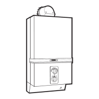
- Unscrew the six screws (A) which hold the water
section to the gas section (see fig. 28).
- Remove the water section complete with the dia-
phragm.
- Remove bearing plate and spindle and grease, (see
Section 6.11).
- Carefully remove and inspect the plastic water sec-
tion top cover.
- Re-assemble in reverse order.
NNOOTTEE
: Fit the water governor last. It is easier if the
cold water inlet connection is partially engaged befo-
re fitting the screws and reconnecting the union nuts.
FFiigg.. 2288
77..66 PPiieezzoo UUnniitt CCaarr
ttrriiddggee
- Disconnect the spark electrode lead from the piezo
unit cartridge.
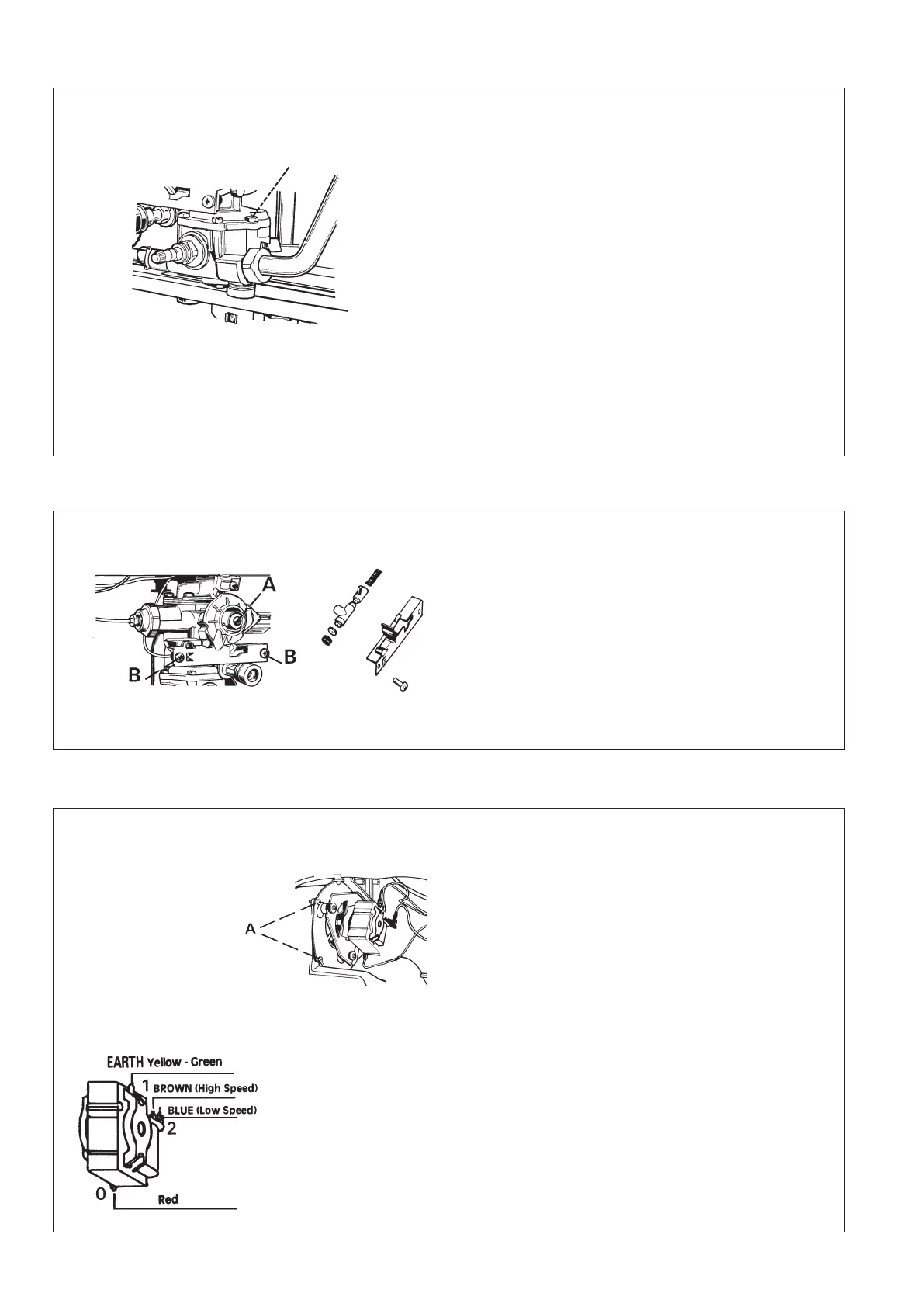
- Remove the screw holding the gas control cam and
remove the cam (A) (see fig. 29).
- Remove the two screws (B) holding the retaining
plate.
- Remove the piezo cartridge and renew.
- On reassembling ensure that the locating pins on
each end of the spring are correctly engaged in
their location holes.
FFiigg.. 2299
77..77 FFaann AAsssseemmbbllyy
- Disconnect electrical connectors from assembly.
Note positions.
- Remove the two screws and washers (A) securing
the fan assembly to the flue hood (see fig. 30).
- Release wiring loom from support clip.
- Gently ease the fan assembly away from the flue
hood disengaging lug at rear of fan assembly.
- Re-assemble in reverse order.
Note : The dimension - back plate to fr
ont face of
impellor is : -57.5 mm +0.5 mm -0.0 mm.
FFiigg.. 3300
A
 Loading...