19
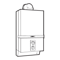
77..88 TToo RReeppllaaccee FFuussee oorr PPCCBB
Isolate electrical supply :
((AA)) FFUUSSEE ::
- Pull out fuse holder (A) from board and
s
lide fuse out of holder (see fig. 31).
((BB)) PPCCBB ::
-
Remove connections (fan, microswitch,
pressure switch).
-
Disconnect mains supply cable from ter-
minals.
-
Remove two nuts and washers (B) retai-
ning thermocouple and conductor lead.
-
Remove fuse and ease board from plas-
tic retaining clips.
- Remove four screws and remove PCB.
- Re-assemble in reverse order.
FFiigg.. 2277
77..1100 TToo rreeppllaaccee pprreessssuurree sswwiittcchh
- Isolate electrical supply.
- Remove two screws securing plastic turret cover.
- Pull off tag connectors from terminals.
- Remove low pressure tube from pressure switch.
- Remove two screws securing pressure switch to
bracket.
- Lift off pressure switch dis-engaging it from the
high pressure tube.
- Remove “O” ring from spiggot on the underside of
the pressure switch.
- Replace in reverse order referring to colour coding
label on top of appliance.
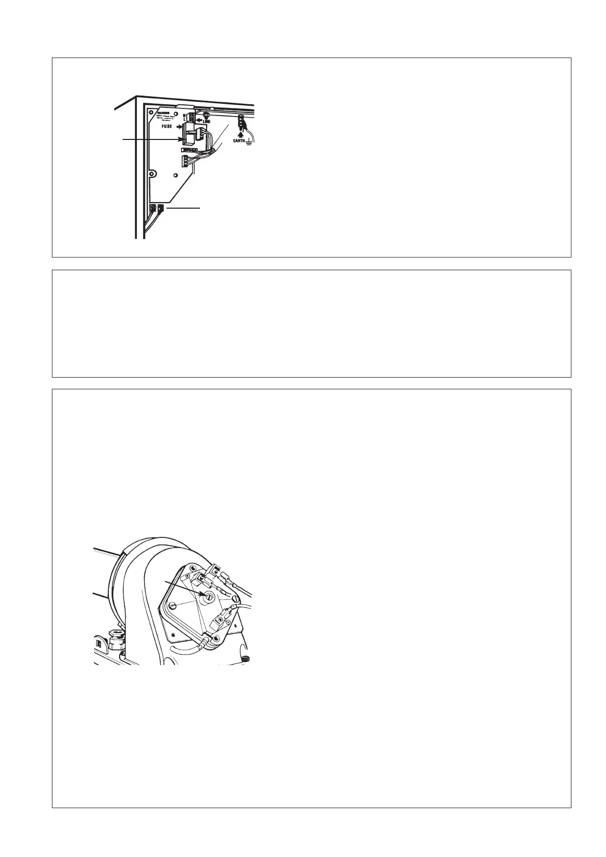
77..1111 AAddjjuussttmmeenntt ooff pprreessssuurree sswwiittcchh
aa))
If a pilot extinction occurs within 10 seconds of turning the hot tap off, it is possible that the pressure switch is
out of adjustment, if the pressure switch remains in the high flow position in excess of 10 seconds after the fan
switches to low speed interruption of the current to the thermoelectric valve occurs.
It is possible to adjust the pressure switch to ensure a rapid return from high to low flow.
AAddjjuussttmmeenntt SSeeqquueennccee ::
- Adjusting the pressure switch.
- Ensure the front case is on.
- Isolate electrical supply.
- Remove two scr
ews securing plastic turret cover
and lift of
f cover
.
- Remove terminal cover from pressure switch expo-
sing the adjusting screw (A) and remove securing
paint (see fig.32).
- Set a multimeter to 240 V scale and connect it
acr
oss the common and one other ter
minal of the
switch.
- Re-establish electrical supply and ensure that gas is
off at gas control.
- Turn on a hot tap to give high fan speed.
- Using a suitable screwdriver screw the adjusting
screw (A) in until changeover of the pressure switch
contacts are observed.
- Screw out adjusting screw (A) 3 turns to achieve the
setting point.
- Check operation of the pressur
e switch (see section 5.5.).
- Replace the plastic terminal cover on the pressure
switch.
- Replace the plastic turret cover and fixing screws.
bb))
If main burner extinction occurs during hot water demand, it is possible that the pressure switch is out of
adjustment. Scr
ew adjusting scr
ew (A) out until flush with top of moulding, then follow adjustment sequen
-
ce above.
FFiigg.. 3322
A
A
B
 Loading...