20
77..1122 RReeppllaacceemmeenntt ooff MMiiccrroosswwiittcchh
- Isolate electrical supply.
- Part connector plug on leads to microswitch.
- Remove two lock nuts (4 mm) from microswitch
retaining screws (C) (see fig. 33).
- Remove screws securing microswitch.
- Remove switch together with plastic insulating
plate.
- Renew microswitch and replace in reverse order.
NNOOTTEE ::
Microswitch is not available on its own.
Microswitch Assembly must be used therefore ins-
tructions not detail changing whole assembly.
FFiigg.. 3333
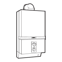
77..1133 AAddjjuussttmmeenntt ooff MMiiccrroosswwiittcchh ooppeerraattiinngg mmeecchhaanniissmm
- Re-establish electrical supply - leave gas cock and hot water taps off.
- Temperature selector can be set in any position.
- Slacken locking screw (B) see diagram in 7-12 - using 1,5 mm hexagon key.
- Turn adjusting screw (A) anti-clockwise until high speed fan operation is obtained.
- The fan should now be at high speed.
- Turn adjusting screw clockwise slowly until low speed fan operation is obtained
- Continue turning adjusting screw clockwise for a further 1/2 turn
- Tighten locking screw.
- Check operation of microswitch (see section 5.4).
77..1144 TToo rreeppllaaccee tthhee GGaass aanndd WWaatteerr SSeeccttiioonn
- Remove the burner (see Section 6.2).
- Disconnect microswitch by parting plug connector on leads.
- Remove the conductor lead at thermoelectric valve (see Section 7.3).
- Remove thermocouple lead at PCB.
- Remove spark electrode lead from piezo cartridge (see Section 7.6).
- Disconnect the gas union at rear of gas section.
- Disconnect the water connections fr
om the water section these ar
e the mains inlet and water section to hea-
ting body
.
- Remove the two screws securing the burner base to the rear chassis.
- Re-assemble in reverse order.
77..1155 TToo rreeppllaaccee CCeerraammiicc LLiinneerrss iinn HHeeaattiinngg BBooddyy
- Remove the burner (see Section 6.2).
- Remove two threaded screws (A) (Section 6.4), which secure the top front panel of the heating body to the
flue hood.
- Remove six self tapping screws (B) (Section 6.4), from front panel of heating body.
- Slide out front and side ceramic liners from locating channels.
- Ease heat exchanger forward to allow rear ceramic liner to be lifted clear of lower channel.
- Lift panel and withdraw lower edge first.
- Re-assemble in reverse order.
C
 Loading...