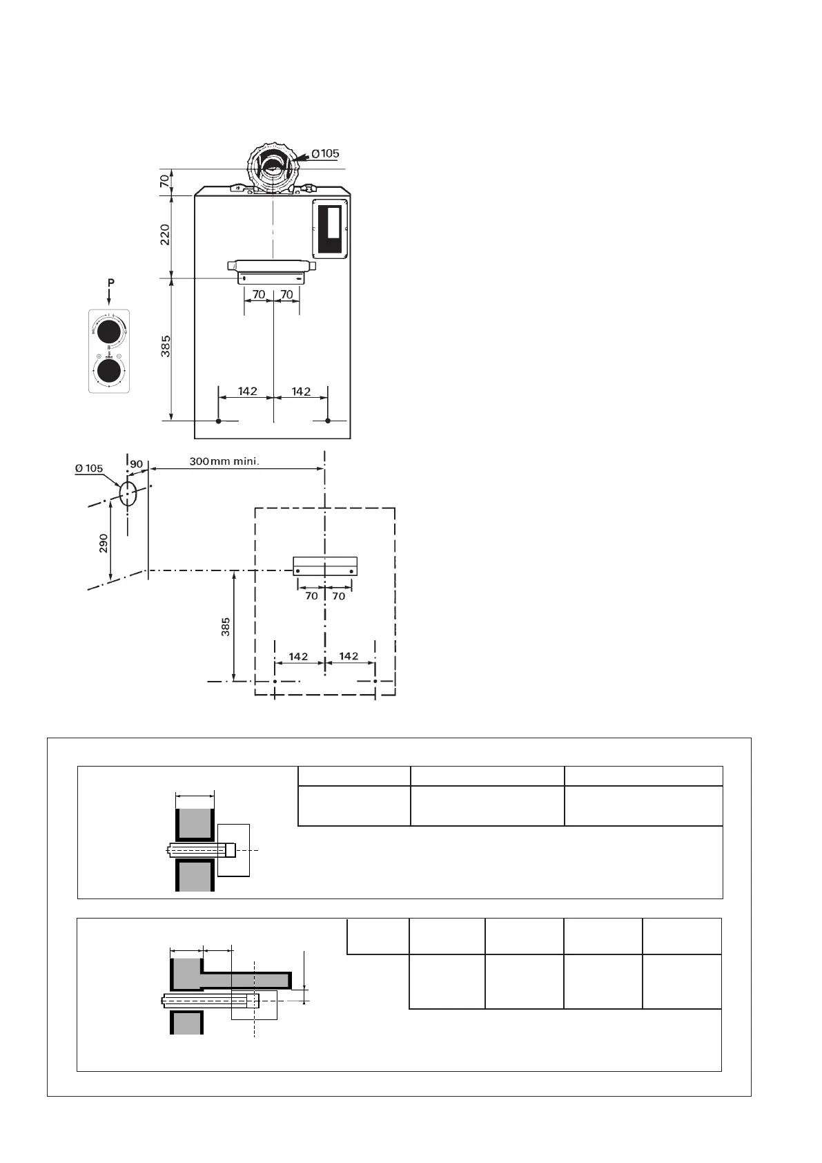
33..33 FFlluuee LLeennggtthh
Minimum Wall Thickness 3 in (75 mm)
8
FFiigg.. 66
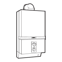
33..22 PPrreeppaarriinngg aanndd ffiittttiinngg tthhee aapppplliiaannccee
PPrreeppaarraattiioonn ::
- Remove the bottom trim by pulling forwards.
- Slide the controls facia plate (P) upwards to disen-
gage from retaining bracket.
-
Release the front case by removing the four fixing
screws and washers positioned at the top, bottom
and centre of appliance.
- Remove the front case by lifting off the top locating
lugs and pulling forward to clear the water section
at the base of the appliance.
NNOOTTEE ::
A template is not supplied with this appliance.
Particular care is therefore necessary to ensure that
the appliance mounting bracket is fitted level and
positioned accurately. When using extended flues,
a fall fo 5 mm per metre length should be provi-
ded. (Fr
om turret to terminal) (see Fig. 5).
- Refer to the drawings opposite for rear and side flue
applications and/or to the dimensions given.
- Set out an drill hole 290 mm (11.4 in) accurately
mark position for bracket.
- Drill and plug the wall.
- Fix bracket to wall using No. 12 screws provided,
ensuring that the bracket is level. If necessary
adjust bracket, finally secure in position.
- Hang the appliance on the bracket, and re-check for
level. Mark bottom fixing holes, removes applian-
ce, drill and plug the wall to suit No 12 screws.
- Re-hang appliance and secure with screws provi-
ded.
Rear Outlet Wall thickness Up to 612.5 mm Over 612.5 mm
Delivered with Extension available
appliance
Pt No 1008520
Flue duct length = wall thickness + 25 mm
Air inlet duct length = wall thic
kness + 25 mm
Pt No. 1008520
Side Outlet EM Up to 500 mm 1401 mm 2300 mm
+ DM 500 mm to 1400 to 2300 to 2787
Deliv
.
1 e
xtern. 2 extern. 3 extern.
With Pt No 2 x 3 x
appliance
1008520 1008520 1008520
EM
= Wal thickness Flue duct length EM + DM + 130 mm
DM = Distance from w
all to case
Air inlet duct length EM + DM + 130 mm
FFiigg.. 55
3.5 ins
 Loading...