9
EN
CHAPTER 5
SETTING UP
INSTALLA
TION
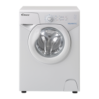
Move the machine near its
permanent position without
the packaging base.
Cut tube-holding straps.
Unscrews the two top screws
A and remove the cover,
sliding it off horizontally.
Remove the cardboard
protection.
Unscrews the two tie braces
B on the crosspiece (with an
H. 19 spanner) and remove
the polystyrene spacers C
under it.
Please do not fit the 2 tie
braces B again!
IMPORTANT:
DO NOT REMOVE THE
SPACERS ABOVE THE
CROSSPIECE.
Replace the cover with the
two screws A.
Please ensure when fitting
the table top the locating
pins are inserted correctly in
their slots, positioned on the
side of the cabinet as shown
in the relevant diagram.
WARNING:
DO NOT LEAVE THE
PACKAGING IN THE
REACH OF CHILDREN AS
IT IS A POTENTIAL
SOURCE OF DANGER.
8
EN
CHAPTER 4
MAXIMUM WASH
LOAD DRY
NORMAL WATER LEVEL
POWER INPUT
ENERGY CONSUMPTION
(PROG. 90°C)
POWER CURRENT FUSE
AMP
SPIN
r.p.m.
WATER PRESSURE
SUPPLY VOLTAGE
TECHNICAL DATA
kg
9÷13
1300
1,4
10
min. 0,05
max. 0,8
220 - 240
l
W
kWh
A
SSEEEE RRAATTIINNGG PPLLAATTEE
MPa
V
3,5
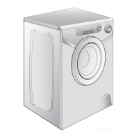
70 cm
51 cm
43 cm
EL
K 4
KK
K
( 90°)
( / )
EL
K 5
.
K
.
A
.
B
( 19
H)
.
HMANTIKO: M
.
A.
B
.
:
K K
XOMENO
TH YKEYAIA
IOTI MOPEI
NA AOTEEEI
MEITO KYNINO