EN-24
Under any circumstances, make sure the Induction cooker hob is well ventilated
and the air inlet and outlet are not blocked. Ensure the Induction cooker hob is in
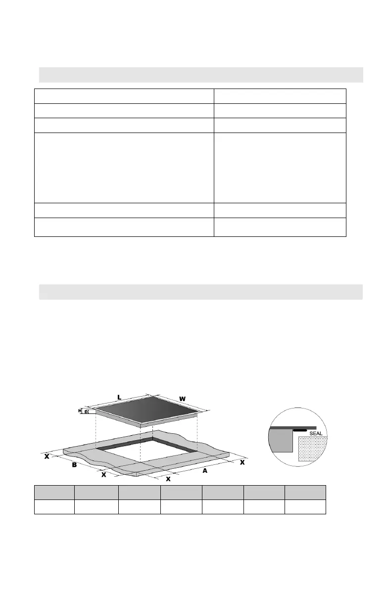
good work state. As shown below
Note: The safety distance between the hotplate and the cupboard above
the hotplate should be at least 760mm.
A(mm) B(mm) C(mm) D E
760 50 mini 20 mini Air intake Air exit 5mm
Before you install the hob, make sure that
• the work surface is square and level, and no structural members interfere with
space requirements
• the work surface is made of a heat-resistant material
• if the hob is installed above an oven, the oven has a built-in cooling fan
• the installation will comply with all clearance requirements and applicable
standards and regulations
• a suitable isolating switch providing full disconnection from the mains power
supply is incorporated in the permanent wiring, mounted and positioned to
comply with the local wiring rules and regulations.
The isolating switch must be of an approved type and provide a 3 mm air gap
contact separation in all poles (or in all active [phase] conductors if the local
wiring rules allow for this variation of the requirements)
• the isolating switch will be easily accessible to the customer with the hob
installed
• you consult local building authorities and by-laws if in doubt regarding
installation
• you use heat-resistant and easy-to-clean finishes (such as ceramic tiles) for the
wall surfaces surrounding the hob.