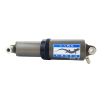
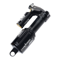
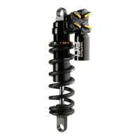
AD-5 Shock Instructions
The Cane Creek AD-5 rear shock is a combined spring and damper system for rear suspension mountain bikes.
The shock utilizes pressurized air as both the springing and damping medium. The unit is typically filled with air
to a pressure between 110 and 250 psi (7.6 - 17.2 bar), depending on the weight and preferences of the rider. The
springing system is like a conventional air spring, where the spring force is generated by reducing the volume of
the pressurized air chamber, thereby increasing its internal pressure. The damping forces are generated by
flowing the pressurized air into and out of several internal chambers through valves as the shock is compressed
and extended. This valving is tuned specifically for each frame design. The AD-5 system also incorporates a
negative spring air chamber which assists the initial travel and provides very smooth performance.
Setup and adjustments:
The springing and damping characteristics of the AD-5 shock are controlled by air pressure. The air pressure is set
based on the weight of the rider and the desired performance characteristics. Pressure is controlled with a
standard shock pump, which should be capable of over 200 psi (13.8 bar) and have a pressure gauge. The shock
should be inflated as indicated on the following chart (above). After some riding, this initial pressure setting can
be adjusted up or down to suit the rider’s preferences. Reduced pressure will provide a smoother, more “plush”
ride, but with a greater tendency to bottom out. Increased pressure will give a firmer ride with somewhat quicker
rebound.
ATTENTION: Use a metal cap with seal to prevent leakage of air from the valve. Inflate or deflate shock
only while it is installed on the bike.
Recommended Maintenance:
Proper care for the AD-5 rear shock includes checking the pressure periodically, keeping the shaft and exposed
rod wiper clean, and occasionally lubricating the seals. Remember that some air will be lost whenever the
pressure is checked. Lubricating the seals is a fairly simple process requiring only a few simple tools, and is
recommended after approximately 200 hours of use.
Servicing the AD-5:
Section A: Shock Disassembly and Seal Replacement
For periodic maintenance or if the shock
is not holding pressure, it can be
disassembled and serviced easily. If the
shock is losing pressure, apply soapy
water to the exterior of the shock prior
to disassembly. The bubbles formed will
indicate the leak’s location. We recom-
mend ordering a seal kit before opening
the shock. The kit contains the seals and
grease required to properly rebuild the
shock. Call a Cane Creek technical service representative at 800-234-2725.
1. Deflate the shock and clamp the valve end of the shock in a soft-jawed vice, being careful not to damage the
shock’s eyelet (Figure 1).
2. Unscrew (counterclockwise) the black, lock ring in the middle of the shock. DO NOT USE TOOLS (pliers, vice
grips, etc.) Wrapping a cloth or large rubber band around the ring will improve your grip.
3. Carefully pull the piston shaft out of the large cylinder. Prevent contamination of the seals by keeping all parts
clean and free of dirt.
4. Remove the lock ring from the piston shaft by sliding it over the eyelet end. The seal bushing can also be
removed in the same manner (Figure 2).
5. Remove the rod wiper from the lock ring (Figure 5), the seals from the seal bushing (Figure 6), and the AD0303
o-ring seal from the piston (Figure 7). Be very careful not to scratch the seal grooves while removing the seals.
Wipe all the surfaces using a clean lint-free cloth (Do not use solvent). Liberally apply Cane Creek Defriction Lube
to the seal grooves and the new seals. Install the seals as shown in Figure 5, 6, and 7. In order to modify the
shock’s valving setup, please refer to section B.
6. If the “soapy water” test revealed a leak around the bushing (AD0127) in the piston shaft eyelet, then the
volume adjustment plate must be removed to replace the seals. If the test did not show a leak around the
bushing you can skip to step 10.
7. To remove the volume adjustment plate, clamp the piston shaft eyelet in the vice, and use a spanner wrench to
unscrew (counterclockwise) and remove the piston (Figure 3). With the piston shaft still clamped in the vice,
remove the white plug in the center of the volume adjustment plate. Insert the hooked tool into the plate’s
opening and carefully pull it upward being careful not to damage the plate. Work from side to side not allowing
the plate to become jammed within the shaft (Figure 4).
Rider’s Weight Shock Pressure Rider’s Weight Shock Pressure Rider’s Weight Shock Pressure
lbs. (kilos) psi (bars*) lbs. (kilos) psi (bars*) lbs. (kilos) psi (bars*)
100 (45) 110 (7.6) 150 (68) 160 (11.0) 200 (91) 210 (14.5)
110 (50) 120 (8.3) 160 (73) 170 (11.7) 210 (95) 220 (15.2)
120 (54) 130 (9.0) 170 (77) 180 (12.4) 220 (100) 230 (15.9)
130 (59) 140 (9.7) 180 (82) 190 (13.1) 230 (104) 240 (16.5)
140 (64) 150 (10.3) 190 (86) 200 (13.8) 240 (109) 250 (17.2)
* 100 kPa = 1 bar
Seal Kit
Soft-jawed Vice
Required Tools:
3mm
Spanner Wrench
Lint free cloth
Figure 1
Figure 2
Figure 3
Figure 4
Figure 5
Figure 6
Figure 7
Figure 8
piston shaft
lock ring
wire ring
large
cylinder
spanner wrench
piston
seal
bushing
piston shaft
lock ring
rod wiper
AS0125
lock
ring
O-ring
AD0108
O-ring
AD0108
quad ring
AD0301
seal bushin
valve screw
valve
shim
piston
O-ring
AD0302
O-ring
AD0303
hooked
tool
plug
volume adjustment
plate
piston
shaft
retaining
ring
volume
adjustment
plate
O-ring
AD0106
washer
O-ring
AD011