EasyManuals Logo

Canon A-1 Repair Guide

Canon A-1
176 pages
To Next Page IconTo Next Page
To Previous Page IconTo Previous Page
Page #150 background imageLoading...
Page #150 background image
84
4.1
OPT
IC
Adjustment
1.
Offset
voltage
check
1)
Desolder
one
end
of
resistor
RTC.
2)
Short
OPT
pin
7 (E)
to
8
(MOS
OUT)
.
3)
Measure
the
voltage
from
pin
6 (TP)
to
ground
(Vl).
4)
Measure
the
voltage
from
pin
8
(MOS
OUT
to
ground
(V2)
5)
If
V2
is
within
±0.2
mV
of
Vl,
no
adjustment
is
necessary
.
Pig.
~-2
2.
Offset
Adjustment
If
V2
is
not
within
0.2
mV
of
Vl,
adjust
in
the
follow-
ing
manner
.
Fig.
4-3
1)
Remove
res
i
stor
R N
ULL
ADJ .
and
replace
it
temporarily
with
an
approximately
30Rn
variable
resistor.
2)
Adjust
the
variable
resistor
until
Vl
and
V2
are
within
±2
mV
of
each
other.

Table of Contents

Other manuals for Canon A-1

Questions and Answers:

Question and Answer IconNeed help?

Do you have a question about the Canon A-1 and is the answer not in the manual?
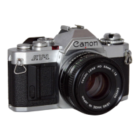
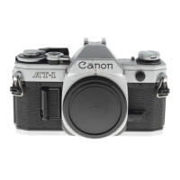
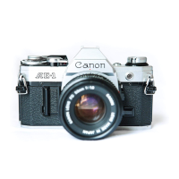
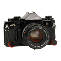
Canon A-1 Specifications

General IconGeneral
Type35mm SLR
Lens MountCanon FD
MeteringCenter-weighted average
Focusing ScreenInterchangeable
Flash Sync1/60s
Weight620g (body only)
Dimensions141 x 92 x 48 mm
Shutter Speed30s - 1/1000s, Bulb
ISO Range6 - 12800
ViewfinderEye-level pentaprism
Exposure ModesProgram, Aperture-priority, Shutter-priority, Manual
Film AdvanceManual
Film RewindManual
Battery4LR44 or 4SR44
ShutterHorizontal cloth focal-plane

Related product manuals