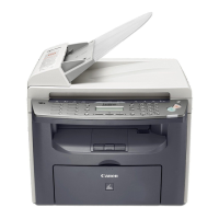
Do you have a question about the Canon i-SENSYS MF4330d and is the answer not in the manual?
| Print Technology | Laser |
|---|---|
| Functionality | Print, Copy, Scan, Fax |
| Print Resolution | 600 x 600 dpi |
| Monthly Duty Cycle | 30, 000 pages |
| Display | LCD |
| Paper Capacity | 250 sheets |
| Duplex Printing | Yes |
| Scanner Type | Flatbed |
| Scan Resolution | 600 x 600 dpi |
| Copy Resolution (Black) | 600 x 600 dpi |
| Fax Transmission Speed | 33.6 kbps |
| Connectivity | USB, Ethernet |
| Operating System Compatibility | Windows, Mac |
Provides overview of product specifications, including parts, safety, and function lists.
Covers safety precautions for laser mechanisms, toner, and battery handling.
Details specifications for the host machine, ADF/DADF, and FAX functionalities.
Lists various functions and parameters like scanning and recording ranges.
Explains the machine's construction and function configuration.
Details the basic operation sequence of the machine's components.
Outlines the fundamental construction and components of the original exposure system.
Provides instructions for replacing parts within the original exposure system.
Explains the basic operation of the ADF and DADF units.
Covers how the machine detects and handles paper jams in the feeding system.
Details parts and procedures for removing ADF and DADF components.
Outlines the laser scanner assembly and its basic configuration.
Describes control of the laser scanner motor speed and fault detection.
Provides steps for replacing the laser scanner unit.
Explains the image formation system overview and configuration.
Details the driving and control of the high-voltage system for image formation.
Instructions for replacing the transfer charging roller.
Describes the pickup and feed system overview and its components.
Details the various types of paper jams detected and their outlines.
Procedures for replacing parts like the main motor and pickup roller.
Outlines the fixing system's configuration and specifications.
Explains control mechanisms, particularly temperature control of the fixing unit.
Details the protection functions implemented to prevent fixing heater runaway.
Procedures for replacing the fixing unit and fixing film unit.
Overview of the machine's control panel and its layout.
Details the power supply route and protection functions.
Step-by-step instructions for removing external covers and internal components.
Information on parts that require periodic replacement.
Cleaning procedures for various parts of the machine.
Procedures for basic adjustments like paper margin and reading alignment.
Lists and outlines electrical components such as motors, sensors, and PCBs.
Provides an overview of how error codes are used to indicate machine faults.
Lists specific error codes, their causes, and recommended remedies.
Introduces the Service Mode and its capabilities for setting service data.
Details various soft switch settings and their functions.
Explains how to operate test modes for functions like printing and sensor checks.
Lists service tools, including solvents and lubricants, and their uses.


