Do you have a question about the Canon imageRUNNER 3570 and is the answer not in the manual?
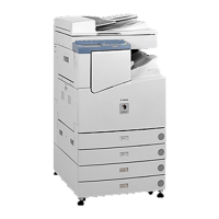
Details about the Cassette Feeding Unit-Y1/Y2.
Explains the symbols used in the documentation to indicate special information like notes, cautions, and errors.
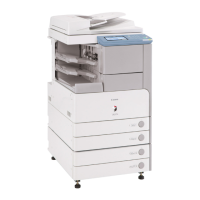
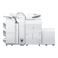
Discusses the overall system configuration, including delivery accessories and their types.
Details machine specifications such as paper accommodation, dimensions, power supply, and weight.
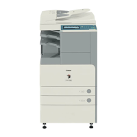
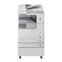
Identifies and labels the external components of the machine with corresponding numbers.
Explains basic operations like turning the power on/off and using the control panel interface.
Lists and describes configurable settings accessible via the User Mode, covering common settings and adjustments.
Provides instructions for user-level maintenance tasks such as cleaning.
Covers crucial safety information regarding laser light, toner, and electrical hazards.
Details technical specifications like paper accommodation, dimensions, and power consumption.
Lists the various functions the machine offers, such as printing and copying speeds.
Outlines essential checks before installation, including site requirements and environmental conditions.
Provides step-by-step instructions for unpacking the machine and installing it.
Details the process of safely removing packaging from the machine and its components.
Explains the procedure for installing the toner bottle correctly.
Guides the user through the process of installing the drum unit.
Details how to properly secure the main copier unit to its base or pedestal.
Instructions for connecting necessary cables, including power and network.
Explains the procedure for stirring toner to ensure proper distribution.
Guides on setting up paper cassettes, including paper size and type selection.
Outlines the process for APVC correction to calibrate the drum.
Provides instructions for adjusting horizontal and vertical image position for accurate printing.
Explains how to verify network connectivity and settings, including PING tests.
Offers solutions for common network connection issues.
Describes how to perform test prints and check image quality and overall operation.
Provides instructions for installing a card reader accessory.
Outlines the procedure for installing the NE Controller.
Guides the user through unpacking and checking the contents of the shipping box.
Details the step-by-step procedure for installing the unit.
Explains the procedure for safely turning off the host machine before installation.
Guides the removal of various covers and the right door.
Provides instructions for installing the 3 Way Unit-A1.
Details the procedure for mounting covers and the right door after installation.
Guides the user through checking the machine's operation after installation.
Outlines the final checks, including connecting power and making test copies.
Covers the removal of external covers like rear, right, front, and lower right covers.
Guides the removal of the 3 Way Unit, including its internal components.
Details the drive system, including motors and solenoids.
Explains the removal of the cassette pickup motor 3 and related components.
Guides the removal of the cassette pickup motor 4.
Covers the removal of various parts within the document feeding system.
Details the removal of the delivery roller 2.
Guides the removal of the reversing roller.
Explains the procedure for removing the delivery roller 3.
Guides the removal of the duplexing inlet roller.
Details the removal of the inlet roller.
Covers the removal of various electrical components like sensors and PCBs.
Guides the removal of the delivery sensor 2.
Details the removal of the delivery tray 2 paper level sensor.
Explains the removal of the reversal sensor.
Guides the removal of the duplexing inlet sensor.
Details the removal of the delivery sensor 3.
Guides the removal of the delivery solenoid 1.
Explains the procedure for removing the delivery solenoid 2.
Details the removal of the delivery solenoid 3.
Guides the removal of the 3 Way Unit Controller PCB.
Covers periodic replacement of parts, durables, and scheduled servicing.
Lists parts requiring periodic replacement for sustained performance.
Mentions parts that may require replacement due to wear or damage, with estimated lives.
Notes that the 3-Way Unit-A1 does not have parts requiring scheduled servicing.
Provides an overview of the electrical components and their arrangement.
Details the arrangement and functions of electrical components like motors and sensors.
Describes the specifications, control mechanisms, and functions of the laser exposure system.
Details the specifications of the laser light, scanner motor, and polygon mirror.
Outlines the basic operational sequences for the laser scanner and laser unit.
Covers various control mechanisms related to the laser exposure system.
Details how laser activation timing is controlled using signals from the DC controller PCB.
Explains the APC control mechanism for maintaining laser light intensity.
Describes how the laser scanner motor speed and revolution are controlled.
Explains how the laser shutter operates in conjunction with the machine covers to block laser light.
Provides instructions for replacing components of the laser exposure system.
Guides the user through the process of removing and replacing the laser scanner unit.
Details the specifications and major components of the image formation system.
Lists specifications for drum unit, primary charging, transfer charging, and pre-exposure unit.
Explains the overall process of image formation, including outlines and detailed steps.
Outlines the basic operational sequences for initial rotation and copying.
Explains mechanisms used to stabilize image output, such as drum film thickness and developing bias control.
Covers the specifications and charging mechanism of the drum unit.
Explains the function of the drum cleaner unit.
Covers the specifications of the developing unit, including cylinder diameter and development method.
Describes the toner cartridge construction and its role as a hopper.
Covers the outline of the transfer unit, including its components and bias control.
Covers the transfer guide bias control.
Describes the process of cleaning the photosensitive drum.
Provides step-by-step instructions for replacing various parts.
Describes the specifications, controls, and functions of the pickup/feeding system.
Outlines the basic operational sequences for paper pickup and feeding.
Covers methods and sensors used for detecting various types of paper jams.
Describes the functionality and components of the cassette pick-up unit.
Describes the functionality and components of the manual feed pickup unit.
Covers adjustments related to horizontal registration.
Explains paper movement in duplex mode.
Provides step-by-step instructions for replacing various parts of the pickup/feeding system.
Describes the specifications, control mechanisms, and functions of the fixing system.
Outlines the power-on and down sequences of the fixing system.
Covers various control mechanisms related to the fixing system.
Explains how fixing film speed is controlled in response to low temperature and rotation.
Details temperature control during start-up, copying, and in response to paper size and double-sided copying.
Describes the fixing film cleaning process and its timing.
Explains how paper passage is detected in the fixing unit.
Outlines the protective mechanisms like thermo switch, triacs, and relays.
Provides step-by-step instructions for replacing components of the fixing system.
Guides the removal and replacement of the fixing unit.
Details the procedure for removing the pressure roller.
Explains how to remove the cleaning roller.
Guides the removal and replacement of the fixing film.
Details the removal of internal delivery sensors.
Explains the procedure for removing the fixing film sensor.
Describes the components and functions of the control panel, including LCD and touch panel.
Explains the machine's counters that track printouts.
Identifies the fans used in the machine and their functions.
Describes the power supply units and their distribution within the machine.
Explains the route of power and the functions of various PCBs.
Lists the ratings and tolerances for the printer unit power supply PCB.
Details the protective mechanisms like thermo switch and relays that prevent over-current.
Describes the lithium battery for power backup and its replacement.
Explains energy-saving modes like standby and sleep.
Provides instructions for replacing various parts of the external controls and power supply system.
Guides the removal and replacement of the main drive assembly.
Details the procedure for removing the power supply unit, including covers and PCBs.
Guides the removal and replacement of the control panel assembly.
Explains the procedure for removing the control panel LCD unit.
Details the steps for removing the DC controller PCB.
Guides the removal of the control panel inverter PCB.
Explains the procedure for removing the control panel key switch PCB.
Details the steps for removing the control panel CPU PCB.
Guides the removal of the all-night power supply PCB.
Explains the procedure for removing the controller power supply PCB.
Details the removal of the option power supply PCB.
Guides the removal of the high-voltage PCB.
Explains the procedure for removing the exhaust fan.
Details the removal of the main drive assembly motor.
Guides the removal of the fixing driver motor.
Explains the procedure for removing the right door.
Details the removal of the circuit breaker.
Defines MEAP as Multifunctional Embedded Application Platform and its Java-based architecture.
Explains the MEAP counter for tracking function usage and application installation.
Describes the components of a MEAP application, including UI, OS, and Java VM.
Lists parts requiring periodic replacement for sustained performance.
Refers to parts that may need replacement due to wear or damage, with estimated lives.
Outlines the basic procedures for scheduled servicing, including checks and cleaning.
Provides detailed instructions for cleaning various parts of the machine.
Covers standards and procedures for adjusting image quality, including margins and position.
Covers adjustments after replacing CIS or reader controller PCB.
Details adjustments after replacing the laser scanner unit.
Covers adjustments after replacing the developing unit or drum unit.
Lists adjustments after replacing electrical components like HDD, DC Controller PCB, etc.
Covers adjustments related to the pickup and feeding system, including horizontal registration.
Outlines initial checks to perform before troubleshooting faulty images.
Provides troubleshooting steps for common image faults and malfunctions.
Addresses specific image quality issues like uneven density and white lines.
Covers troubleshooting for general machine malfunctions.
Lists various electrical components like clutch/solenoid, motors, and PCBs.
Provides a comprehensive table of error codes with their names and descriptions.
Provides detailed information on error codes, including cause and remedy.
Lists error codes related to SEND functions, including network and server issues.
Provides a detailed list of jam codes categorized by unit.
Provides a list of alarm codes and their descriptions.
Details error codes specific to the finisher.
Lists error codes specific to the DADF unit.
Provides an overview of the service mode structure and its layers.
Explains the three-layer screen construction of the service mode.
Guides on how to enter service mode and navigate its options.
Covers how to view machine status.
Explains how to view input/output status.
Covers various adjustment modes for copier, feeder, and sorter.
Provides detailed adjustment procedures for copier settings.
Details adjustments for feeder settings.
Explains adjustments related to the sorter.
Covers various functions for operation and inspection.
Details functions related to the copier.
Explains functions related to the feeder.
Covers machine settings like paper size and temperature control.
Explains how to perform test prints.
Explains how to view various counters for service and usage data.
Lists special tools required for servicing, in addition to standard tools.
Provides a list of oils and solvents used for maintenance and their properties.
| Brand | Canon |
|---|---|
| Model | imageRUNNER 3570 |
| Category | All in One Printer |
| Language | English |