Do you have a question about the Canon imageRUNNER C1030 and is the answer not in the manual?
Explains symbols used in the documentation to indicate special information.
Details the system configurations for various options and functions.
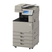
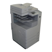
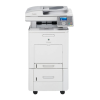
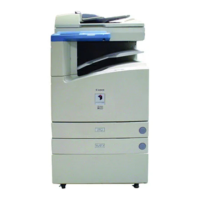
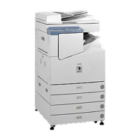
Provides names of parts, external views, cross-sections, and product details.
Covers checking the installation environment, points to note, and contents before installation.
Outlines procedures for unpacking, installing parts, securing the product, and connecting cables.
Details procedures for verifying network connectivity, including ping operations and troubleshooting.
Provides instructions for installing a card reader, including notices and registration procedures.
Outlines the procedure for installing a handset, including points to note and checking contents.
Details the procedure for installing memory, including checking contents and before/after installation steps.
Provides an overview of the main controller's configurations and functions.
Describes the sequence of operations for setting up the machine.
Explains the overview of image flow and the construction of the image processing module.
Details the flow of image data for various functions like copy, SEND, and fax.
Provides instructions for replacing specific parts, such as the Main Controller PCB.
Covers the fundamental construction and major components of the original exposure system.
Details the basic sequences of operation at power-on and in response to start key presses.
Explains various control mechanisms like lamp control, enlargement/reduction, and dirt sensor control.
Provides instructions for replacing ADF and Reader unit components.
Outlines the basic construction and overview of the original feeding system.
Explains the operation modes and document size detection for the ADF.
Details the overview of jam detection and various types of jams that can occur.
Covers procedures for removing the ADF unit, pickup feed unit, rollers, motors, and separation pad.
Provides an overview of the laser exposure system's configuration.
Explains controls related to laser emission, intensity, masking, and failure detection.
Details the overview and failure detection of the laser scanner motor.
Provides instructions for removing the laser scanner unit.
Describes the overview of the image formation system and its print process.
Explains various controls for stabilizing image quality, including environmental and color corrections.
Details the overview of toner cartridges, level detection, memory tag control, and detection.
Explains the ETB unit, automatic bias control, and transfer roller engagement/disengagement.
Provides procedures for replacing components like drum motor, main drive unit, and solenoids.
Provides an overview of the pickup/feed system, including its components and control by DC controller.
Explains controls for cassette pickup, manual feed pickup, skew correction, and throughput-down.
Details the overview of jam detection and lists various jam codes and conditions.
Explains the overview and control of duplex feeding, including the role of the reverse driver PCB.
Provides procedures for replacing components like pickup feed unit, rollers, and motors.
Provides an overview of the fixing system, including its configuration and components.
Explains controls for fixing temperature, pressurizing, and releasing.
Details protective functions for the fixing assembly, including CPU and heater safety circuit controls.
Provides procedures for replacing the fixing unit, sleeve unit, drive unit, and motor.
Provides an overview of the DC controller, including its operation of each block, fan/motor control, and failure detection.
Gives an overview of the control panel's components and functions.
Details the counter system, including different models and counter types.
Explains the low-voltage power unit, protection functions, and energy-saving functions.
Provides procedures for replacing external covers, controller boxes, PCBs, fans, and other components.
Provides an overview of the e-Maintenance/imageWARE Remote system and its monitored information.
Details the setting procedure for e-Maintenance/imageWARE Remote, including network and proxy settings.
Offers troubleshooting steps for communication test failures with UGW.
Lists service cautions related to E-RDS settings and main controller board replacement.
Provides an overview of Embedded RDS (E-RDS) and its features/benefits.
Details the setting procedure for e-Maintenance/imageWARE Remote, including network and proxy settings.
Lists communication error codes and strings with their causes and remedies.
States that the machine does not have parts requiring periodical replacement.
Lists consumable parts and their expected service life.
States that the machine does not have parts requiring periodic servicing.
Covers procedures after replacing the copyboard glass and reader unit.
Details checking the nip width of the fixing pressure roller.
Provides procedures after replacing DC controller PCB, main controller PCB, clearing RAM data, and control panel.
Outlines the procedure after replacing the ADF unit.
Lists initial checks to perform before diagnosing malfunctions, including installation environment and paper checks.
Explains how to perform test prints to check printer engine operation.
Provides an outline of electrical components, including clutches/solenoids, motors/fans, sensors, switches, and PCBs.
Provides a table of error codes, detail codes, and their names/explanations.
Gives detailed explanations of error codes related to fixing assembly, ETB motor, drum motors, and fixing motor.
Lists jam codes for the main body and ADF, including jam types and conditions.
Details alarm codes, specifically for the ADF.
Provides an outline of fax error codes, including user and service error codes.
Covers preface and procedure for entering the special management mode, including menu list.
Details troubleshooting steps such as pre-checks, user requests, paper errors, and image errors.
Covers service mode configuration, exiting service mode, backup, and screen operation.
Details the copier functions, including display, I/O, adjust, function, option, and counter settings.
Covers feeder functions such as adjust and function settings.
Details fax functions including SSSW, MENU, NUM, NCU, and TESTMODE settings.
Explains test modes for system, scan, print, fax, and panel operations.
Provides an overview of the upgrade process, including firmware structure.
Details required system environment and steps before performing the upgrade.
Explains the procedure for downloading system software and firmware.
Lists special and standard tools required for servicing the machine.
Identifies special tools like digital multimeter and tester extension pins.
Lists standard tools such as screwdrivers, pliers, and rulers.
Provides a list of special tools required for servicing, categorized by their necessity.
Lists standard tools required for servicing the machine.
Provides a list of solvents and oils used for cleaning and lubrication.
| Print Resolution | 1200 x 1200 dpi |
|---|---|
| Scan Resolution | 600 x 600 dpi |
| Copy Resolution | 600 x 600 dpi |
| Functions | Copy, Print, Scan |
| Print Speed (Black) | 30 ppm |
| Multiple Copies | 1 to 999 |
| Duplexing | Standard |
| Standard Paper Capacity | 550 sheets |
| Acceptable Paper Sizes | Letter, Legal, Statement, Executive |
| Power Consumption | 1.5 kW |
| Color Capability | Full Color |
| Network Connectivity | Ethernet |