Do you have a question about the Canon imageRUNNER 2545 Series and is the answer not in the manual?
Regulations concerning laser products manufactured on or after August 1, 1976, and sale of uncertified products.
Precautions when servicing areas around the laser assembly, especially regarding covers with warning labels.
Precautions when servicing areas around the laser assembly, especially regarding covers with warning labels.
The machine turns on when the main power switch is turned on, excluding low power or sleep modes.
Instructions on safely turning off the machine, especially regarding download processes.
Information about toner being non-toxic, and warnings against throwing it into fire or contact with plastic.
Warnings about the risk of explosion if batteries are replaced by an incorrect type and proper disposal.
Servicing instructions require turning off the power source according to specified steps and disconnecting the power plug.
Information on the product series and model types, including print speeds and configurations.
Highlights key features of the product, such as user-replaceable waste toner containers and high image quality.
Details on technical specifications including copyboard, light source, media, noise levels, power, dimensions, and weight.
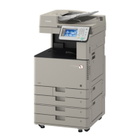
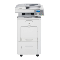
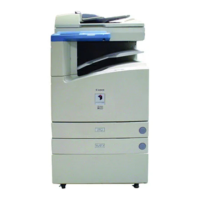
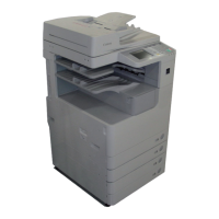
Identifies and labels external and internal components of the machine.
Describes the two types of power switches: main and control panel, and how they function.
Details the functions of the main power switch and the control panel power switch.
Provides instructions on turning the machine on/off and important notes to follow during these operations.
Outlines the main functional system blocks of the machine, including exposure, controller, image formation, fixing, and pickup systems.
Describes the components and functions related to the original exposure system.
Explains the architecture and functionality of the machine's controller system.
Details the components and operation of the laser exposure system.
Describes the process and components involved in forming the image.
Explains the system responsible for fixing the toner image onto the paper.
Details the mechanism responsible for feeding paper into the machine.
Explains the Embedded Remote Diagnosis System and its features.
Describes actions required after replacing parts like CCD unit, copyboard glass, and stream reading glass.
States that there are no consumables listed.
States that there are no specific service precautions listed.
Provides a functional configuration overview of the controller system, detailing its main components like PCBs and memory.
Details the main controller PCB and its components like image memory, flash ROM, SRAM, and ports.
Details the construction of the laser exposure system, including laser light and scanner motor specifications.
Lists specifications, controls, and functions for laser light, scanner motor, and polygon mirror.
Identifies the main components of the laser exposure system, such as the laser unit and mirrors.
Details the specifications and mechanisms of the image formation system, including photosensitive drum, primary charging, developing, and transfer units.
Lists specifications like material, diameter, cleaning method, and process speed for components.
States that there are no components listed for replacement.
States that no periodical service is listed.
States that no specific points to note are listed.
Introduces the on-demand fixing method used by the machine.
Highlights the machine's introduction of the on-demand fixing method.
Details fixing method, speed, heater type, control temperature, and detection methods.
Describes the pickup feed system's paper storage and pickup methods.
Lists paper storage, pickup methods, stack capacity, paper types, grammage, size switch, and duplexing method.
Shows an illustration of the arrangement of rollers within the pickup feed system.
Describes areas related to controls like Cassette Pickup Assembly, Multi-Purpose Pickup Assembly, and Fixing/Registration Assembly.
Details the overview of the cassette pickup assembly, paper size detection, and paper presence detection.
Provides a categorized list of parts, including external covers, main units, PCBs, solenoids, motors, fans, switches, clutches, and others.
Lists external covers that can be removed for parts replacement or cleaning.
Lists major units and parts of the machine for replacement.
Details consumable parts that require periodic replacement.
Lists the various PCBs within the machine.
Lists the solenoids used in the machine.
Lists the motors used in the machine.
Lists the fans used in the machine.
Lists the switches used in the machine.
Lists the clutches used in the machine.
Lists other miscellaneous parts.
Step-by-step instructions for removing the reader's left cover, noting the use of screws.
Instructions for removing the reader's front cover after opening the platen cover, noting screw usage.
Steps for removing the support cover, involving opening the right cover and releasing claws.
Steps to remove the right cover assembly, involving several previous cover removals and a belt.
Instructions for entering service mode to adjust laser unit values after replacement.
Steps for removing the toner supply assembly, involving multiple component removals.
Service mode procedures for adjusting white plate data and DF white level after replacing the platen glass.
Service mode procedures for adjusting DF white level after replacing the ADF scan glass.
Steps for removing the transfer roller, involving opening the right cover and removing bearing.
Procedure for removing the separation static charge eliminator, involving opening the right cover.
Steps for removing the waste toner container, involving opening the front cover and turning a lock lever.
Steps for removing the main controller PCB, involving cover removals, connector disconnections, and screws.
Actions after replacing the image processor PCB, including firmware download and entering service label values.
Steps for removing the reader relay PCB, involving rear cover removal and flexible cables/connectors.
Steps for clearing DC controller settings, RAM, and entering service mode items after replacement.
Steps for removing the fixing film unit, involving cover, fixing assembly, and plate removal.
Introduces the section on adjustment procedures, including those for replacing parts and image position.
Describes adjustments required after replacing components in the scanning system, controller system, and laser exposure system.
Details procedures for adjusting basic image position, such as margins and non-image areas.
Provides a checklist for initial troubleshooting, covering site environment, paper, and system components.
Explains how to perform test prints to diagnose image failures.
Lists common troubleshooting items categorized by image failure and operation failure, with references.
Outlines methods for upgrading system software for the host machine and inner finisher.
Introduces the chapter describing various codes displayed when a failure occurs, classified into error, jam, and alarm codes.
Lists and explains various error codes, their causes, and remedies for machine faults.
Details jam codes, their types, and associated sensor names and IDs for the main unit.
Lists alarm codes with their titles and associated movements, causes, and measures.
Provides an overview of the service mode, explaining its purpose and how it is accessed.
Details various service mode functions like #SSSW, #MENU, #NUMERIC, #SCAN, #PRINT, #NETWORK, etc.
Guides on how to verify the installation procedure, including checking parts and symbols.
Details on selecting the site of installation and environmental conditions for proper machine setup.
Provides important points to consider before installation, such as dew condensation and machine weight.
Outlines the correct sequence for installing various optional components.
Instructions for checking the contents of the installation package for various options.
Steps for unpacking the machine and removing packaging materials, including handling the machine's weight.
Procedure for installing the Document Tray-J1.
Procedure for installing the Card Reader.
Procedure for installing the Serial Interface Kit-J2.
Procedure for installing the Control Interface Cable-A1.
Lists items needed for relocating the machine, such as fixing tape and drum cover.
Instructions on preparing for relocation, including precautions when lifting with a double-cassette pedestal.
Steps for relocating the machine, including removing the drum unit and securing covers.
Lists special tools required for service, including digital multimeter and tester extension pins.
Provides circuit diagrams for various parts of the machine, divided into multiple parts.