5
5
5-2
5-2
Adjustment > Outline > Image position adjustment
Adjustment > Outline > Image position adjustment
Outline
Adjustment when replacing parts
This section describes adjustment required in eld service works when replacing parts.
The parts are classied by function into the following 3 blocks.
Category
Replacing parts Reference
Scanning
System
CCD unit
“Action to Take after Replacing the CCD Unit”(page 5-3).
Copyboard glass
“Action to Take after Replacing the Platen Glass”(page 5-4).
ADF reading glass
“Action to Take after Replacing the ADF Scan Glass”(page
5-4).
Controller
System
Main controller PCB
“Action to Take after Replacing theMain Controller
PCB”(page 5-5).
DC controller PCB
“Action to Take when Replacing the DC Controller
PCB”(page 5-5).
RAM PCB
“Action to Take after Replacing the RAM”(page 5-5).
Laser Exposure
System
Laser scanner unit
”Action to Take after Replacing the Laser Scanner
Unit”(page 5-5).
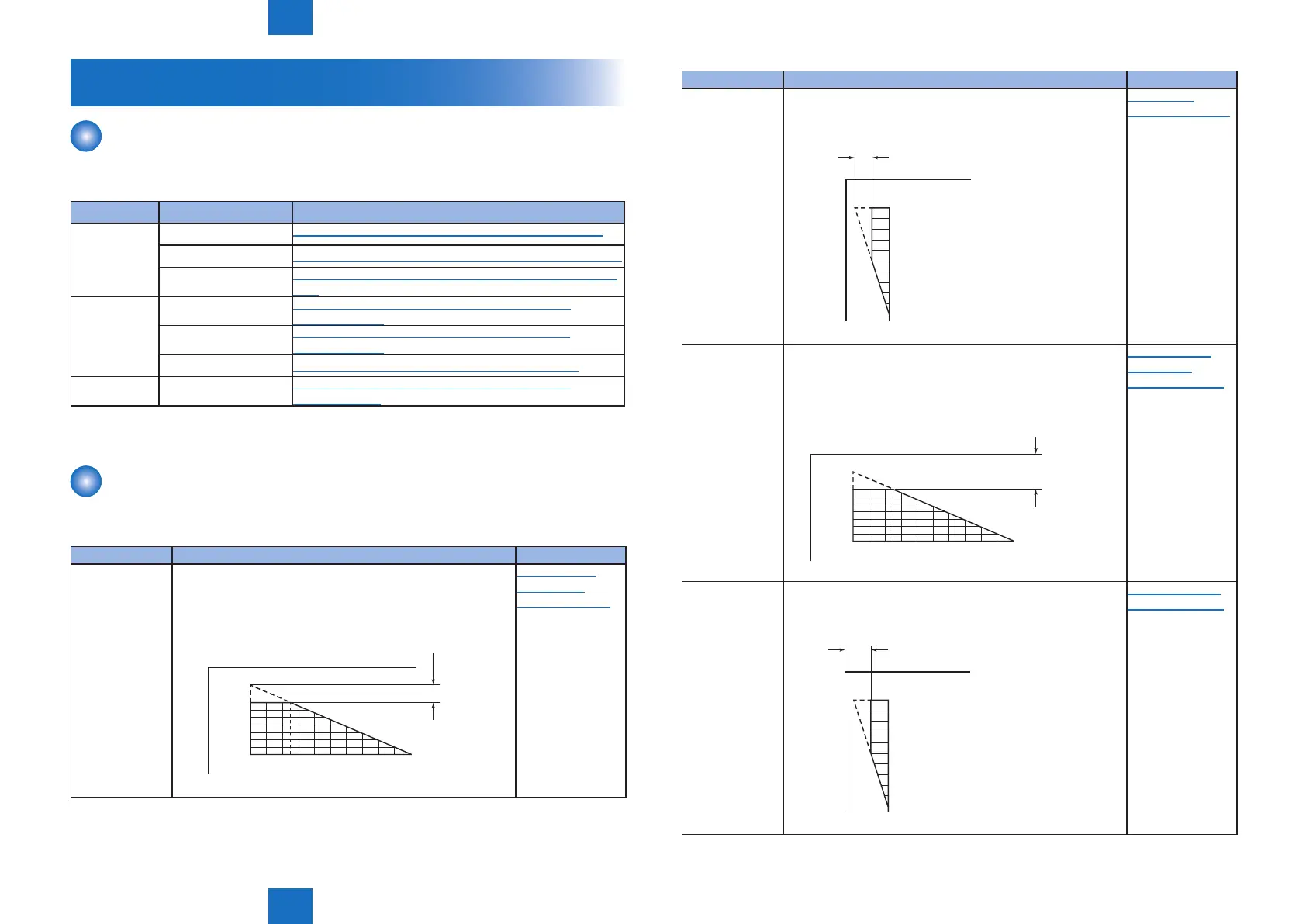
Image position adjustment
This section describes procedures when adjusting basic image position (image margins,
nonimage area, etc).
Category Item Reference
Margin Along the
Leading Edge
Single-sided copy: 2.5 ± 1.5 (mm)
Double-sided copy: 2.5 ± 2.0 (mm)
2 54 6 8 10 12 14 16 18 200
2.5+/-1.5mm
(2nd side of double-sided copy
: 2.5+/-2.0mm)
“Margin Along
the Leading
Edge”(page 5-6).
T-5-1
Category Item Reference
Left Image MarginSingle-sided copy: 2.5 ± 1.5 (mm)
Double-sided copy: 2.5 ± 2.0 (mm)
10
8
6
5
4
2
0
2.5+/-1.5mm
(2nd side of double-sided copy:
2.5+/-2.0mm)
“Left Image
Margin”(page 5-6).
Leading Edge
Non-Image Width
Single-sided copy: 2.5 ± 1.5 (mm)
Double-sided copy: 2.5 ± 1.5 (mm)
2 54 6 8 10 12 14 16 18 200
2.5+/-1.5mm
(2nd side of double-sided copy:
2.5+/-1.5mm)
“Leading Edge
Non-Image
Width”(page 5-6).
Left Non-Image
Width
Single-sided copy: 2.5 ± 1.5 (mm)
Double-sided copy: 2.5 ± 1.5 (mm)
10
8
6
5
4
2
0
2.5+/-1.5mm
(2nd side of double-sided copy:
2.5+/-1.5mm)
”Left Non-Image
Width”(page 5-7).
T-5-2
 Loading...