2
2
2-13
2-13
Technology > Original Exposure System > Controls > Image Processing
Technology > Original Exposure System > Controls > Image Processing
- Between sheets
The machine does not move CCD.
It reads the original using the position determined at the end or start of a job; however,
if the presence of dust is still detected at the position, the machine will execute image
correction.
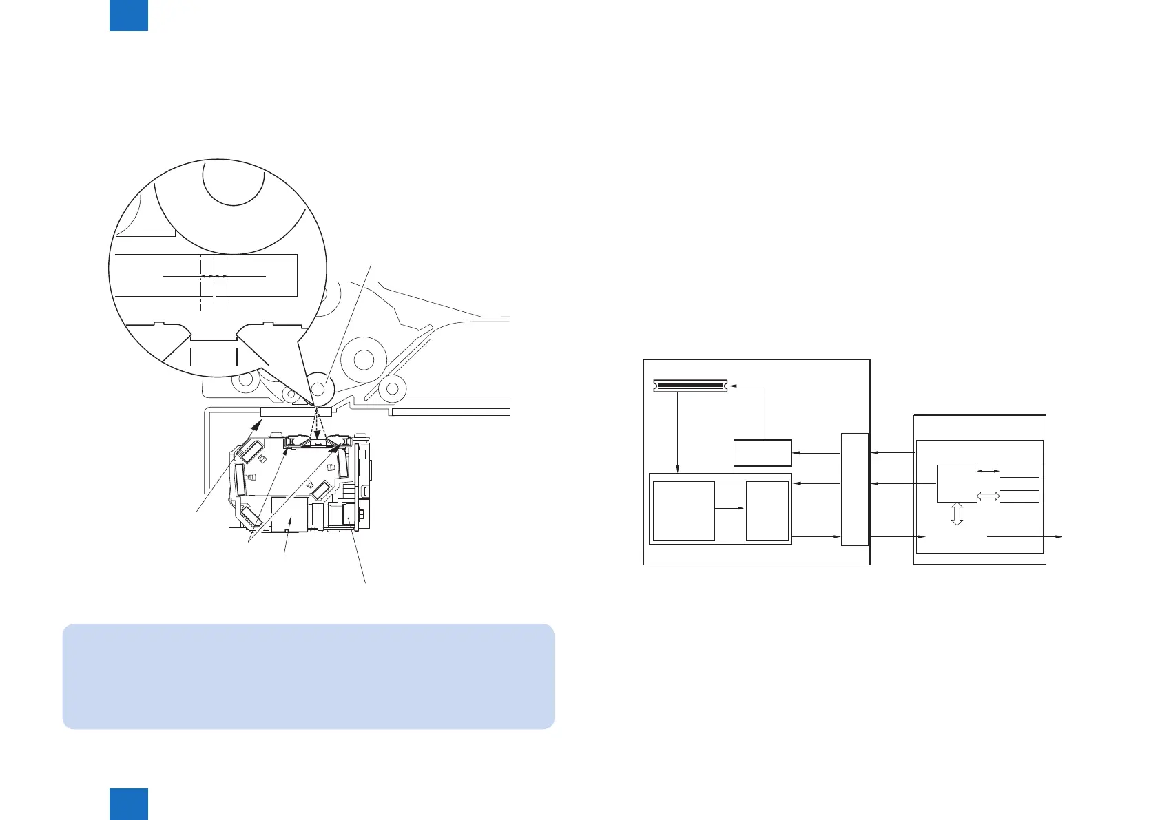
Platen roller
0.5mm0.5mm
A B C
Lens
LED
CCD
Stream
reading glass
Service Mode
(Lv1) COPIER > OPTION > IMG-RDR > DFDST-L1
(used to adjust the dust detection level between sheets)
(Lv1) COPIER > OPTION > IMG-RDR > DFDST-L2
(used to adjust the dust detection level at the end of a job)
F-2-26
■
Image Processing
●
Overview
The functions of image processing system’s PCB are described below.
- Main controller PCB CCD drive, analog image process, A/D conversion, shading
correction (executed per each job), shading adjustment (executed at
power-on)
- CCD PCB Analog image process, A/D conversion
The machine uses the main controller PCB to process images for every single image line.
Specic functions are as follows.
a. Main controller PCB
- Shading correction
b. CCD PCB (inside CCD unit)
- CCD drive
- CCD output gain correction, offset correction
CCD(4lines )
Analog image
signal
Analog image
process
- gain correction
- offset
correction
A/D
conversion
CCD drive
control
CCD/AP PCB
CCD
control
signal
Gain
correction
data
Digital
image
signal
Main controller PCB
CCD PCB
Digital image
signal
EEP-ROM
SRAM
CPU
Shading
correction/
adjustment
ASIC
F-2-27
 Loading...