Do you have a question about the Canon Inner Finisher-L1 and is the answer not in the manual?
Information regarding the manual's purpose, scope, and applicability across different localities.
Details Canon's process for issuing corrections and new editions for the manual.
Lists registered trademarks and their owners relevant to the product and manual.
States the copyright ownership and restrictions on copying or translation of the document.
General caution regarding the handling and supervision of the manual's contents.
Defines symbols used in the service manual and their meanings.
Essential safety guidelines and warnings to be observed before commencing service work.
Precautions for safe and effective cleaning of components using solvents.
Guidelines for safe and correct procedures during assembly and disassembly of the device.
Instructions on proper screw tightening to avoid damage to parts, especially with thin plates.
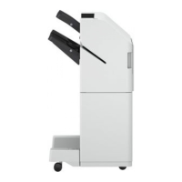
Highlights the key capabilities and functionalities of the Canon Inner Finisher-L1.
Details the technical specifications of the finisher and its components, including paper handling.
Provides an illustrated breakdown of the finisher's external and internal components.
Explains the finisher's structure, functional blocks, and electrical control system.
Lists the various controls and functions available within the finisher system.
Describes the fundamental paper feeding and stacking operations of the finisher.
Details the components and operation of the feed unit.
Explains the functions of the processing tray unit, including alignment and stapling.
Covers the stack tray's shift, paper height, and full detection mechanisms.
Lists and describes various jam codes and their causes.
Details the power distribution and protective functions within the finisher.
Outlines periodic maintenance tasks, intervals, and references for the finisher.
Provides essential precautions before replacing finisher parts.
Guides the user through detaching the finisher from the host machine.
Details procedures for removing and replacing external covers.
Explains removal/replacement of major internal components.
Describes removal of the paper trailing edge pushing guide solenoid.
Details procedures for removing specific motor components.
Outlines steps for removing and replacing various sensor components.
Provides instructions for removing the Finisher Controller PCB.
Covers removal procedures for miscellaneous parts like the return belt unit.
Summarizes adjustment procedures, service mode settings, and use cases.
Details fundamental adjustments for paper alignment and staple position.
Explains adjustments needed after replacing components like the Finisher Controller PCB.
Describes the purpose and usage of the service label for recording adjustment values.
Outlines essential preliminary checks for diagnosing machine issues.
Provides a flowchart and details for troubleshooting alignment and staple position issues.
Lists and describes solvents, oils, and special tools for finisher servicing.
Presents the complete electrical circuit diagram for the finisher unit.