Do you have a question about the Canon MF735C Series and is the answer not in the manual?
Essential safety guidelines including laser, toner, battery, and assembly/disassembly.
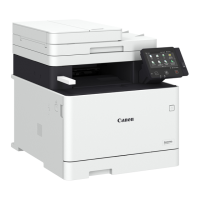
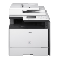
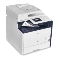
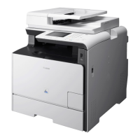
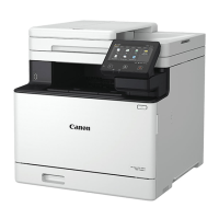
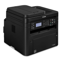
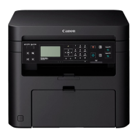
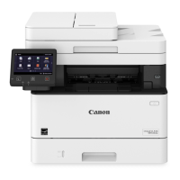
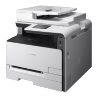
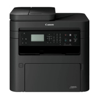
Details on the product series, available models, and key features.
Technical specifications for the main printer unit, including hardware and performance.
Information on supported paper types, sizes, and auto 2-sided printing capabilities.
Diagrams and lists identifying external and internal machine components.
Overview of the machine's six main functional blocks and their interconnections.
Explanation of the CIS, ADF specifications, drive configuration, and detection mechanisms.
Description of the laser scanner unit, functional configuration, and failure detection methods.
Details on main and DC controllers, motor control, and power supply units.
Explanation of major components, image formation process, and high voltage controls.
Details on pickup, feed, delivery systems, parts configuration, and controls.
Explanation of the fixing system, temperature control, protection, and failure detection.
Information for service technicians on the machine's system management.
Details on available firmware upgrade methods: UST, Internet, USB, PCB replacement.
Procedure for backing up and restoring service mode setting values using DCM.
Overview of the E-RDS monitoring program for collecting machine status and failure information.
Information on periodically replaced parts, consumable parts, and required periodical services.
Indicates if the machine requires any specific periodical service.
Identification of major units like ADF/Reader and Host Machine components.
Diagrams showing electrical components like motors, sensors, PCBs, and heaters.
Step-by-step guide for removing external covers like toner cartridge, left/right covers, etc.
Procedures for removing ADF unit, rollers, CIS, and drive units.
Instructions for removing controller cover, PCBs, wireless LAN, and panel units.
Procedures for replacing transfer rollers, ITB unit, density sensor, and motors.
Steps for removing the fixing assembly, power supply unit, and fixing motor.
Guides for removing pickup rollers, separation rollers, motors, and feed units.
Procedures for adjusting components after replacement like control panel, ITB, and PCBs.
Steps for AGC, paper back shading, and DF white level adjustments.
Procedures for adjusting copyboard and ADF geometric and color displacement.
Instructions for performing engine and controller test prints.
Details on various controller test print patterns and their interpretation.
Explanation of cartridge log reports for users and service technicians.
Guidance on recurring faulty images, nip width confirmation, and duplex copy hue differences.
Procedure for collecting debug logs for problem analysis.
Explanation of error, jam, and alarm log indications on the control panel.
List of error codes, detection descriptions, and remedies.
Details on jam codes, sensor names, and areas for host machines and ADF.
Description of alarm codes, including toner bottle empty alarms.
Overview of service mode, access methods, remote UI usage, and operating conditions.
Detailed explanation of COPIER service modes: DISPLAY, ADJUST, FUNCTION, OPTION, COUNTER.
Details on ADJUST and FUNCTION modes for the ADF (FEEDER).
Explanation of SSSW, MENU, NUM, NCU, MODEM, and FACULT service modes.
Detailed descriptions of PRINT, MODE, THRU, NRKE, BLND, DENS, SW, MONOMODE, FEED, START.
Steps for installing the Copy Control Interface Kit-C1.
Procedure for installing the MiCARD Attachment Kit-B1.
Installation guide for the Copy Card Reader-F1.
Lists of special tools and solvents/oils required for servicing.
Diagrams illustrating the machine's electrical circuits.
List of data that can be backed up and restored, categorized by function.
Classification and details of software counters used for tracking machine operations.
| Functions | Print, Copy, Scan, Fax |
|---|---|
| Print Resolution | Up to 1200 x 1200 dpi |
| Copy Resolution | Up to 600 x 600 dpi |
| Maximum Paper Size | A4 |
| Toner saver mode | Yes |
| Greyscales | 256 levels |
| Max. scan width | 216mm |
| Memory | 1 GB |
| Product Type | Laser Multifunction Printer |
| Print Technology | Laser |
| Scan Type | Flatbed, ADF |
| Scan Resolution | Up to 600 x 600 dpi |
| Connectivity | USB, Ethernet |
| Operating System Compatibility | Windows, macOS |
| First Print Out Time | Less than 8.5 seconds |
| Printer languages | PCL6, UFR II |
| Copy modes | Text |
| Reduction / Enlargement | 25% - 400% |
| Other features | Auto duplex |
| Colour scanning depth | 24-bit |
| Compatibility | TWAIN, WIA |
| Media types | Plain Paper, Recycled Paper, Heavy Paper, Label, Envelope |
| Media sizes | A4, A5, B5, Legal, Letter, Executive |
| Interface type | USB 2.0 |