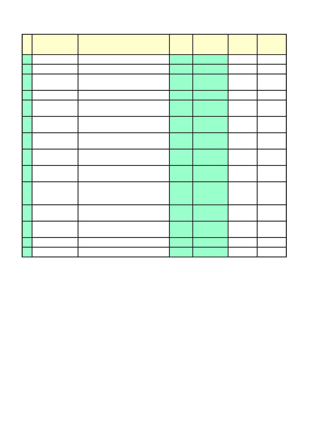
(3) Grease application
1) Printer unit
1 drop = 9 to 18 mg
No Part name Where to apply grease / oil
Drawing
No.
Grease / oil
Grease /
oil amount
(mg)
Number of
drops x
locations
1 Chassis ass'y Entire surface the carriage slider contacts (1) Floil KG107A 27 to 54 3 x 1
2 Adjust plate L Carriage shaft cam L sliding portion (2) Floil KG107A 18 to 36 2 x 1
3 Chassis ass'y
Carriage shaft sliding portion on the left
side of the chassis (1 location)
(3) Floil KG107A 9 to 18 1 x 1
4 Adjust plate R Carriage shaft cam R sliding portion (4) Floil KG107A 18 to 36 2 x 1
5 Chassis ass'y
Carriage shaft sliding portion on the right
side of the chassis (1 location)
(5) Floil KG107A 9 to 18 1 x 1
6 Chassis ass'y
PR lift shaft cam contact portion (3
locations)
(6) Floil KG107A 18 to 27 1.5 x 3
7 Idler pulley
The shaft surface which contacts the
idler pulley hole
(7) Floil KG107A 9 to 18 1 x 1
8 Carriage shaft
Entire surface of the carriage shaft where
the carriage unit slides
(8) Floil KG107A 200 to 400
9
Carriage shaft
spring L
Carriage shaft sliding portion (to the end
of the spring)
(9) Floil KG107A 9 to 18 1 x 1
10 Carriage shaft
Carriage shaft surface where the carriage
unit slides (and where the machine-
application of the grease is not feasible)
(10) Floil KG107A 9 to 18 1 x 1
11 CL gear base
Outer surface of the CL idle gear R
cylinder
(11) Floil KG107A 9 to 18 1 x 1
12 CL gear base
Outer surface of the CL output gear
cylinder
(12) Floil KG107A 9 to 18 1 x 1
13 CL input gear Joint of the CL gear base (13) Floil KG107A 9 to 18 1 x 1
14 CL input gear CL input gear teeth (14) Floil KG107A 9 to 18 1 x 1