Do you have a question about the Canon PC-D320 and is the answer not in the manual?
Details core product capabilities: speed, resolution, power, and USB interface.
Lists technical parameters including general, communication, scanner, printer, copy, and interface specs.
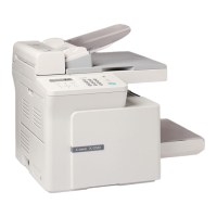
Introduces main machine components, external views, and operation panel functions.
Covers handling, storing, and safety precautions for the toner cartridge and print media.
Identifies and illustrates main internal sections: component layout, PCBs, and sensors.
Details scanner components, their functions, and paper path within the scanner section.
Explains the paper feeding mechanism, pick-up functions, and jam detection configurations.
Covers the laser/scanner, toner cartridge, transfer, and fixing mechanisms of the printer.
Notes the absence of new functions specific to this model.
Critical safety warnings for electrical shock, high temperatures, batteries, fire, and ignition hazards during service.
Provides step-by-step procedures for disassembling and reassembling key machine components.
Lists consumables, cleaning items, inspection, parts, tools, and adjustment items for maintenance.
Detailed instructions for cleaning various internal and external machine parts.
Procedures for checking and performing essential adjustments like nip width and gain auto-adjustment.
Comprehensive guide to diagnosing and resolving machine problems via error codes, messages, and fault conditions.
Explains hardware switches and service data settings for configuring machine functions.
Describes various test modes (D-RAM, Print, Modem, Faculty) for diagnosing machine operations.
Details how to output various service reports for status checks and diagnostics.
Presents a detailed wiring diagram illustrating electrical connections within the machine.
Provides instructions for setting up and checking the initial operation of the machine.
Illustrates the structure and flow of user-configurable settings accessed via the operation panel.
Covers the installation and service operations for optional accessories, specifically the handset kit.
| Resolution | 600 x 600 dpi |
|---|---|
| Multiple copies | 1-99 copies |
| Paper capacity | 250 sheets |
| Copying process | Laser |
| Warm-up time | 0 seconds (from Power Save Mode) |
| Paper size | A4, Letter, Legal |