This document provides installation, operation, and maintenance instructions for Carbolite 1100°C Chamber Furnaces, specifically the ELF models.
Function Description
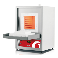
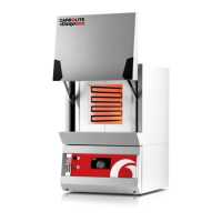
The Carbolite ELF 11/6B and ELF 11/14B models are chamber furnaces designed for heating applications up to 1100°C (2012°F). These "B" versions feature an enclosed heating element within an inner metal chamber, with heating wires partly exposed in the chamber sides to radiate freely into the chamber. The furnaces are equipped with a temperature controller (Carbolite 201 by Eurotherm) to manage heating cycles and maintain desired temperatures. They can operate on single-phase voltages ranging from 200-240V (or 100-120V to order), adjustable via the controller's power limit parameter. An optional overtemperature control system is available for enhanced safety.
Important Technical Specifications
- Maximum Temperature: 1100°C (2012°F)
- Models Covered: ELF 11/6B, ELF 11/14B
- Voltage Range: 200-240V (single-phase) or 100-120V (single-phase, to order)
- Controller: Carbolite 201 (Eurotherm)
- Fuses (200-240V):
- ELF 11/6B: Supply Fuse Rating 10A (2 off), Aux. Fuse 2A*, Customer Fuse Rating 10A
- ELF 11/14B: Supply Fuse Rating 12.5A (2 off), Aux. Fuse 2A, Customer Fuse Rating 12.5A
- Fuses (100-120V):
- ELF 11/6B: Supply Fuse Rating 10A (4 off), Aux. Fuse 2A, Customer Fuse Rating 20A
- ELF 11/14B: Supply Fuse Rating 12.5A (4 off), Aux. Fuse 2A, Customer Fuse Rating 25A
- *Note: Aux. Fuse marked with * is not present unless overtemperature option is fitted.
- Chimney: Short ceramic tubing, approximately 150mm inlet diameter for fume extraction duct.
- Hearth: Ceramic tile.
- Insulation: Light-weight ceramic fibre.
- Safety Features: Door switches interrupt heating element circuit when door is open. Supply light and Heat light indicators.
- Atmospheres: Designed for inert or oxidizing gases only; not gas-tight, residual oxygen levels of 1% are to be expected.
Usage Features
- Installation:
- Lift by the base using two people.
- Place in a well-ventilated room, away from other heat sources, on a non-inflammable surface.
- Maintain at least 50mm free space around the furnace; do not obstruct case vents.
- Ensure quick access to electrical switch-off/disconnection.
- Chimney: Fit ceramic tubing through the top hole if unfitted. For fume-emitting substances, a fume extraction duct (approx. 150mm inlet diameter) can be placed above the chimney outlet. Avoid sealed connections to prevent excessive airflow.
- Hearth: Place ceramic tile on the chamber floor.
- Door Vents: An adjustable plate on the inner door panel allows increased air flow; position as required (see section 7.8 for adjustment).
- Electrical Connection:
- Requires single-phase A.C. supply with earth (ground).
- Check furnace rating label for voltage and amperage.
- Fuse at the next available fuse size equal to or greater than the rating label amps.
- Supply cable fitted to 200-240V models; 110-120V models may require cable connection.
- Connect directly to an isolator or fit with a line plug, accessible to the operator.
- Voltage Level Adjustment: If actual supply voltage differs from label voltage but is within the same range, adjust the controller power limit (section 4.15). Higher voltage requires immediate reduction of power limit to prevent element burnout or fuse blow. Lower voltage makes the furnace underpowered; adjust power limit to regain full power.
- Operation:
- Connect to electrical supply; Supply light glows.
- Operate instrument switch (front panel) to activate controller (I position on, O position off). Controller illuminates and performs a test cycle.
- Close door and adjust temperature controller (section 4.0).
- Heat light glows steadily during heating, then flashes as temperature approaches setpoint.
- To switch off, set instrument switch to O; isolate from electrical supply if leaving off.
- General Operating Notes:
- Avoid prolonged use at maximum temperature to extend heating element life.
- When heating large objects, avoid shielding the thermocouple. Allow large objects to heat at lower temperatures initially.
- Reactive salts may damage wire elements; ceramic hearth protects the floor.
- Open door vents can create cool areas in the chamber.
- Ceramic fibre insulation is fragile; avoid accidental contact. Fine cracks may appear but are usually not detrimental.
- For materials producing smoke/fumes, ensure chimney is fitted and unobstructed. Regularly heat to maximum temperature for one hour without load to burn away soot and prevent electrical breakdown.
- Controller Operation (Carbolite 201):
- Basic Features: Displays measured temperature, output light (heating), timer light. Page key accesses parameter lists (most hidden). Scroll key accesses parameters within a list. Down/Up keys alter setpoint/parameter values.
- Altering Setpoint: From "home" display (measured temperature), press Down or Up to show setpoint, then press again or hold to adjust.
- Stopping/Starting Control: Press Scroll until "m-A" (manual/auto) appears. Press Down or Up to toggle between "mAn" (off) and "Auto" (on). Timer modes 1 & 3 set controller to manual at end of timing.
- Ramp Rate: Press Scroll until "SPrr" (SetPoint ramp rate) is displayed. Use Down or Up to adjust value (degrees per minute). "OFF" cancels ramp rate. "Working setpoint" can be viewed by scrolling to "w.SP".
- Timer Operation (7 modes):
- Mode 1 (Timed dwell and switch off): Starts timing when temp is within 1°C of setpoint. Switches off at end.
- Mode 2 (Timed dwell and stay on): Starts timing when temp is within 1°C of setpoint. Stays on at setpoint at end.
- Mode 3 (Time from cold and switch off): Starts timing immediately (SPrr off) or when working setpoint is within 1°C (SPrr active). Switches off at end.
- Mode 4 (Time from cold and stay on): Starts timing immediately (SPrr off) or when working setpoint is within 1°C (SPrr active). Stays on at setpoint at end.
- Mode 5 (Delayed switch on): Starts timing immediately, control starts at end of timing period. No "END" condition.
- Setting Timer Mode: Scroll to "tm.OP", use Up/Down to alter (OPt.1 to OPt.5). Cannot alter while timer is running; set "StAt" to OFF.
- Setting Time Period:
- Method 1: Scroll to "tmr" (time remaining), use Up/Down to set time (minutes). Automatically activates timer.
- Method 2: Scroll to "dwEl" (dwell time), use Up/Down to set duration. Scroll to "StAt", use Up/Down to set to "run" to activate.
- Stopping Timer: Change "StAt" parameter to OFF.
- End of Time Period: Modes 1 & 3 stop heating (m-A to mAn). Modes 2, 4, & 5 continue heating (m-A to Auto). Modes 1-4 flash "EnD" alarm. Mode 5 has no "EnD" message.
- Cancelling Alarm: Press Page and Scroll together, or change "StAt" to OFF.
*   **User Calibration:** Password-protected (password is 3). Page to "iP", scroll to "CAL.P", use Up to enter password. Scroll to "CAL", use Up/Down to select "FACt" (factory) or "USEr" (user).
    *   Parameters: "Pnt.L" (low temp), "OFS.L" (offset for low temp), "Pnt.H" (high temp), "OFS.H" (offset for high temp). Negative offsets for high readings.
*   **Power Adjustment (OP.Hi):** Reduces effective voltage. Press Page to "oP", Scroll to "OP.Hi". Press Down/Up to display value. Use Down/Up to alter. Do not increase above correct level for supply voltage. Setting to zero prevents heating.
*   **Control at Low Temperatures:** Reduce power limit (e.g., 40%) to improve stability and reduce overshoot. Avoid below 30% as control accuracy falls.
Maintenance Features
- General Maintenance:
- No routine maintenance other than removing soot deposits (section 3.2) and replacing consumables.
- Clean outer surface with a damp cloth; do not allow water into interior. Do not use organic solvents.
- Calibration:
- Recalibration of controller/thermocouple may be needed after prolonged use, especially for accurate readings or near maximum temperature.
- Periodically check with an independent thermocouple and indicator.
- Refer to controller calibration instructions (section 4.14).
- After-Sales Service:
- Carbolite's service division (Thermal Engineering Services) offers repair, calibration, and preventive maintenance.
- Spares available by mail order.
- Quote furnace serial number, model type, and voltage for all correspondence.
- Recommended Spares Kits:
- Available from Carbolite to save time in case of breakdown.
- Each kit includes: one thermocouple and sheath, one solid state relay, one door insulation piece, and one complete heating chamber.
- Repairs & Replacements (Safety Warning: Disconnect from Supply):
- Refractory Fibrous Insulation: Contains refractory fibres. Normal use does not produce significant airborne dust, but higher levels may occur during maintenance/repair.
- Precautions: Use approved mask, eye protection, gloves, long-sleeved clothing. Avoid breaking up waste material. Dispose of waste fibre in sealed containers. Rinse exposed skin with water (not soap/detergent). Wash work clothing separately. Refer to European Ceramic Fibre Industry Association Bulletin No. 11 and UK Health and Safety Executive Guidance Note EH46.
- Temperature Controller Replacement:
- Controller is in the furnace base (remove six screws to separate).
- Wear an anti-static wrist strap to prevent damage.
- Follow instructions supplied with replacement controller.
- Solid-state Relay Replacement:
- Disconnect furnace, remove back panel.
- Note and disconnect wire connections.
- Remove old relay.
- Replace with new relay, ensuring heat-conducting thermal pad or silicon paste is between relay and base panel/aluminium plate.
- Replace panel.
- Thermocouple Replacement:
- Disconnect furnace, remove back panel.
- Note connections (negative leg is blue; compensating cable: negative white, positive green).
- Disconnect thermocouple, withdraw from sheath. Remove sheath and shake out broken pieces.
- Fit replacement, reconnect, observing colour coding.
- Refit back panel.
- Element Replacement:
- Warning: Wear a face mask (section 7.2).
- Element supplied as a complete inner chamber.
- Disconnect furnace, remove back panel, pull chimney.
- Note wiring connections (thermocouple colours, section 7.5).
- Disconnect element power leads and thermocouple connections. Remove thermocouple and support tube.
- Undo four bolts fastening insulation box (under cross supports).
- Carefully slide out insulation box through back of furnace case.
- Slide new insulation box into furnace; DO NOT support by putting hand inside (insulation is fragile).
- Locate fixing holes, replace four bolts.
- Refit chimney, thermocouple support tube, thermocouple.
- Remake all connections. 200-240V models have two heating coils in series; 100-120V models have two in parallel.
- Refit back panel. Run furnace for 30 minutes at 800°C without load to burn off organic binders (smoke may be observed, ensure ventilation).
- Check for proper control to rule out previous fault.
- Door Plug Replacement:
- Lower door fully.
- Loosen four M6 screws on door plug carrier.
- Remove door plug and carrier.
- Remove air inlet blanking plate screws (section 7.8).
- Slide door plug upwards out of carrier.
- Slide new door plug into carrier, align air inlet holes. Reassemble in reverse.
- Air Inlet Adjustment:
- Inlet on inner door panel (door plug carrier) is supplied closed.
- Remove door plug and carrier (section 7.7).
- Remove three screws holding blanking plate.
- Position blanking plate in upper position, clear of air inlet holes, align screw holes.
- Replace three screws to hold blanking plate. Screws must fix door plug into position.
- Fuse Replacement:
- Fuses marked on circuit diagram (section 9.1) with type codes (F1, F2). List of correct fuses in section 9.3. F2 may not be fitted.
- If fuse failed, an electrician should check internal circuits.
- Replace with correct type. Do not fit larger capacity fuses without consulting Carbolite.
- Fuses are near cable entry point, accessed by removing back panel.
- Most models have fuses on an EMC filter circuit board. If four fuses, smaller pair is for control circuit only.
Fault Analysis
- Furnace Does Not Heat Up:
- HEAT light ON: Heating element failed, SSR not working correctly.
- HEAT light OFF: Thermocouple broken/wiring fault, door switch(es) faulty/needs adjustment, contactor faulty, SSR failing to switch on (internal failure, faulty logic wiring, faulty controller).
- No lights glowing on controller: SUPPLY light ON (controller faulty, not receiving supply due to faulty switch/wiring fault). SUPPLY light OFF (check supply fuses, fuses in control compartment).
- Furnace Overheats:
- HEAT light OFF with instrument switch: Controller faulty. Thermocouple shorted/moved out of chamber, mounted wrong way round.
- HEAT light does not go off with instrument switch: SSR failed "ON". Check for accidental wiring fault that overloaded SSR.